
Variometer
On Top
[Disable]
[IAS Speed]
[TAS-Speed]
[GND Speed]
[Altitude]
[Speed2Fly]
[McCready]
[Net. Vario]
[OATemp]
[Heading]
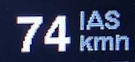
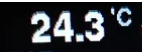

This setting controls which value will be displayed at the right upper digital gauge, per default it is disabled. The above selection allows which values can be shown for that field, such as various speeds like IAS, TAS, GS, the calculated speed to fly according to MC, the MC value itself, the netto vario, OAT temperature, a ‘pseudo’ heading calculated from GPS ground course plus wind.
Bottom
[Disable]
[Altimeter]
[Wind]
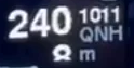

This setting controls which value will be displayed at the right lower gauge, per default the altimeter is displayed there.
This menu allows configuration of screens displayed and individual elements shown there at defined places.
Speed2Fly

[Disable]
[Enable]
Hide or show the command arrows for speed to fly.
Therm.-Assist
[Disable]
[On-Top]
[Heading-Up]
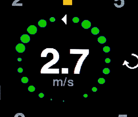
Enable here the thermal assistant to indicate the climb rate within a your circle. It displays colored dots around the center of the display according to the momentary climb rate. Brighter and bigger dots indicate a faster climb rate than darker smaller dots. The reference to the gliders heading can be selected to “On-Top” or to “Heading-Up”.
Flap-Assist
[Disable]
[Enable]
[En.Audio]
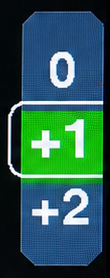
This setting controls whether the flap indication is shown.
The flap assistant indicates the current or optimal flap setting and a green speed band for this flap setting respecting the current wing load.
Depending on a flap sensor being installed, the flap assistant provides different information:
- If a flap sensor is installed, the current flap position label is shown in the middle. As long as the actual flown speed fits to the flap setting the speed band overlaps with the middle section.
- In case no sensor is available, the optimum flap setting is displayed instead.
- In any case, when the audio is enabled the flap position change is also indicated through a recognizable sound overlay.
Battery

[Disable]
[Percentage]
[Voltage]
The battery status display. Options include disable or showing the battery status as a percentage, or as a numeric voltage value without battery symbol.
G-Meter
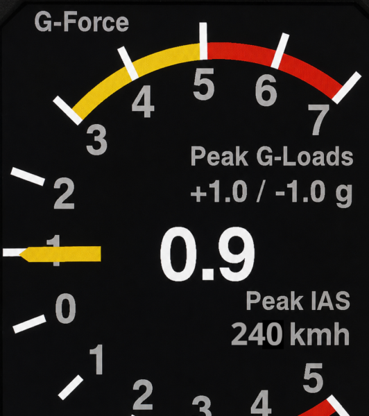
The G-Load Display is an option to show the current load factor acting on the glider. Peak values are stored in flash memory and can be viewed on this display or as well in the setup menu. In addition, the maximum indicated airspeed is displayed. Peak values that exceed the configured limits are shown in red. The sensor sensitivity is setup to measure up to 8 g either positive or negative.
Screen Mode
[Disable]
[Enable]
[Primary]
The G-Meter display can be enabled on demand, or set as a primary screen of the variometer, e.g. for aerobatic flights.
Limits
Red/Yellow positive Limit: [  5.0 / 3.0 ]
Red/Yellow negative Limit: [ -3.0 / -2.0 ]
Extreme Recordings
All peak recordings experienced by the aircraft since the last reset are listed here.
Reset Peak-Hold
[Cancel]
[Reset]
This resets the recorded peak values to zero, clearing all stored peak measurements.
Horizon
[Enable]
[Disable]
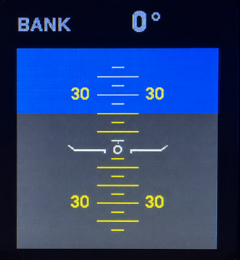
The XCVario, equipped with an Inertial Measuring Unit (IMU) and an Attitude and Heading Reference Systems (AHRS), offers a simple horizon display for situational awareness, similar to the horizon in XCSoar. The display is square and features a pitch scale and the indication of the bank angle on top. Small lines on the scale represent a 5° pitch angle, larger lines indicate 10°.
Once Enabled it can be activated by a button press.
To correct for the specific ground angle of attac and level the horizon display when flying the display has a quick in-page setup feature. A long-press of the rotary button enters the “Pitch Adjust” setup and let you level the pitch of the horizon.
Pitch Adjust: -20°
Important: The horizon is not intended as a blind flight instrument. Instead, it serves as a tool for training and monitoring, such as maintaining the bank angle of e.g. 45° while thermaling. It provides sufficient accuracy for these purposes under normal flight conditions.


