The XCVario has been kept simple in terms of installation and configuration. The installation in the cockpit is therefore easy.
Rear panel Connections
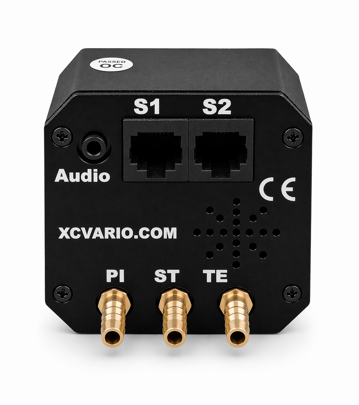
The connections are shown on the right. Except the first series out of 2020 that features only the left RJ45 connector the S1, all recent devices feature two electrical RJ45 connectors S1 and S1. The pin assignment, see the chapter on the RJ45 connectors. The interface S2 has standard IGC assignment, the connection of individual XCVario supplied devices such as the flap sensor or the magnetic sensor and can be done on S2 with 1:1 patch cables. The 80 mm variant has the same rear connections.
Caution: All other devices must be connected via the S2 extender/splitter. A direct connection of a Flarm, for example, to S2 can damage the CAN bus (from XCVario-22).
The supplied wiring harness may only be connected to the S1 socket with the “Vario” labeled plug. Do not connect the Vario plug to the S2 socket either. If voltage is present, this can damage the temperature sensor in the cable on older revisions of the wiring harness.
Also, do not connect the end of the wiring harness that is labeled “Flarm” to the XCVario, this is intended for a Flarm IGC port and should remain unused if Flarm is not used.
Please also note that a possible defect caused by demonstrably faulty wiring is not covered by the warranty.
Pneumatic connections
The pressures required for the XCVario can be connected to the instrument hoses of the mechanical instruments using 6 mm T- or Y-pieces. If these connections are not already available from a previous Vario, the instrument hose can be cut at a suitable point and the connection for the Vario can be made using a T-piece.
Note: A compensation vessel as usually equipped in older installations is NOT needed. Do not connect this to any of the pressure hoses of the XCVario.
You will need:
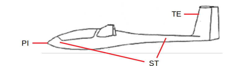
TE:  TE-probe pressure

ST:  Static pressure ( = Static )

PI:  Total Pressure ( = Pitot = overall pressure )
The pressures are usually hosed by the manufacturer behind the instrument panel, and are either already routed there, and can be taken over 1:1 from from a previous device, or can be taken from mechanical instruments using a simple pneumatic T-piece. The pressures for PI and ST are on the airspeed indicator, the TE pressure usually on a mechanical variometer.
Electrical connections
Micro USB
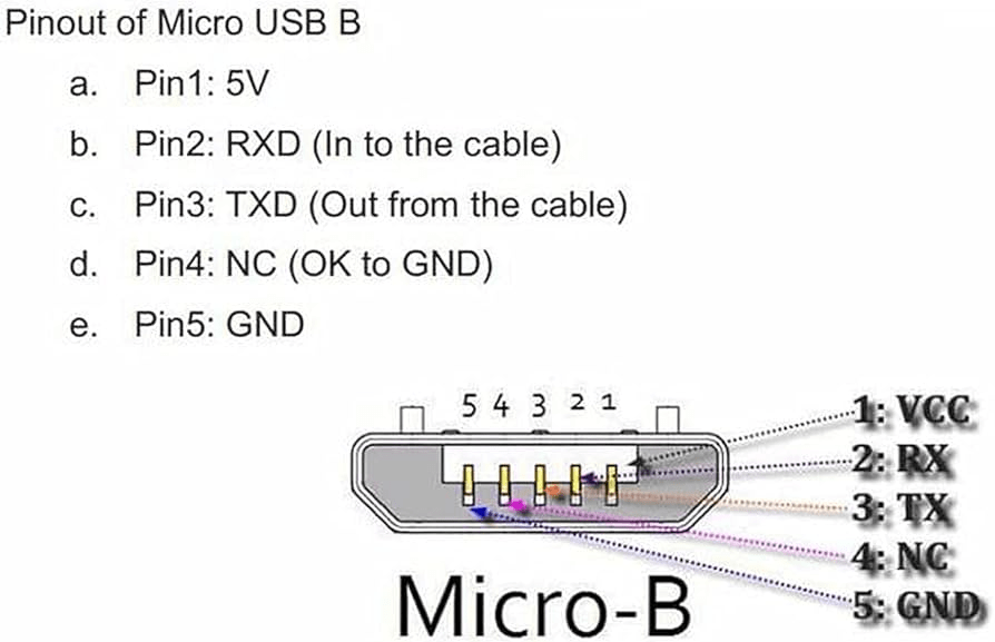
The device is programmed for the first time in the factory via the Micro USB-B connector on the sensor circuit board and is only accessible in the 20 and 21 series when the cover is removed. From the 22 series (57 mm), the USB-B connector is accessible on the top of the device, the opening is sealed with a sticker at the factory. The cable can only plugged in one position, the wider section of the connector is towards the front.
The device can be connected to a PC via USB for diagnostics and can also be supplied with power via the PC. In order to establish contact with the serial interface of the ESP32, drivers for the serial USB converter chip CH340G may be required.
The connection is not required for operation as a variometer, nor for the OTA software update, which takes place via the ESP32 OTA WiFi connection.
Audio Output
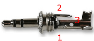
A 3.5mm stereo jack offers an external output for the audio signal of the variometer. Either your own external speaker can be connected to it, or an audio input of a radio device can be used. Normally, the internal loudspeaker of the variometer is sufficient, but it can make sense to be able to hear the signal there, e.g. when operating with headsets, or to connect an external loudspeaker closer to the head in loud cockpits. The internal speaker switches off if an external audio device is plugged in.
Abbildung 1: Audio Stecker The picture on the right shows the necessary audio plug, it is a standard 3.5 mm jack plug with tip, ring, sleeve (TRS), i.e. 3 connections. In the model in the drawing on the right, connector 1 is the tip, 2 is the ring, and 3 is the sleeve. The speaker is connected to connection 1 and 3. Port 2 remains unassigned (NC). If in doubt, measure the connector with a multimeter. The speaker must be connected between the tip and the ground pin.
| Anschluss | Bezeichner | Lautsprecher |
| 1 | Tip, L | connection 1 |
| 2 | Ring, R | NC |
| 3 | Sleeve, GND, Mass | connection 2 |
On the Vario side, the mono audio signal is also applied to connection 2 (ring), so it is not possible to use a mono jack plug (TS) with devices from the 2020 and some 2021 series, as this does not have an isolated ring between connection 2 and 3, and connects connection 2 to ground. From the 4/2021 series, i.e. devices from September 2021, the Vario signal is only output on connection 1, the alternative use of a mono plug is then possible.
RJ45 connector S1
The standard shippment includes a cable tree the XCVario FLARM cable that features a ready-made temperature sensor, a plug for standard applications (standard IGC assignment, e.g. as with most FLARMs and loggers), and an open cable end for a S2F switch. The cable can also be obtained from the shop.
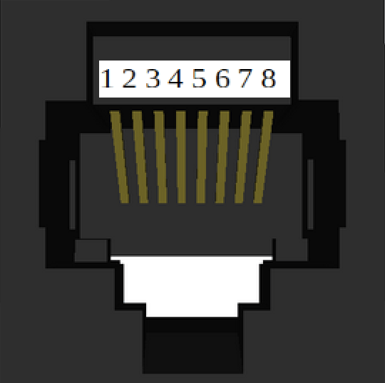
Caution: The assignment at connection S1 with S2F switch and temperature sensor does not have an IGC assignment but is XCVario-specific and different from S2. The XCVario FLARM cable converts the assignment on the S1 appropriately, so that the IGC standard assignment (RJ45) required for the FLARM is available at the end of the FLARM cable. The RJ45 socket is shown in the figure above in a plan view from the rear. Pin 1 is therefore on the far left. The minimum connections required to operate the device in its basic function are shown in bold.
Interface S1
| Pin# RJ45 FCC | Identifier | Direction | Cable colors 568B |
| 1 | Plus 8..28 VDC | Power In | orange-White |
| 2 | RS232 TTL RX | Signal In | orange |
| 3 | RS232 TTL TX | Signal Out | green white |
| 4 | Vario/Speed to Fly Switch | Signal In | blue |
| 5 | T-Sensor +3.3 VDC | Power Out | blue White |
| 6 | T-Sensor Data | Signal Out | green |
| 7 | GND | Power In | brown-white |
| 8 | GND | Power In | braun |
Temperature sensor
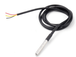
The temperature sensor must be connected to the three pins 5, 6 and 7 provided with the RJ45 cable of the corresponding color. The temperature sensor is part of the FLARM cable.
The temperature sensor is a ready-made Dallas DS18B20 sensor with a waterproof casing and a 1 meter long cable. The sensor has three colored lines, which are usually coded with the colors red, yellow and black. If you use your own sensor, the manufacturer’s instructions must be observed.
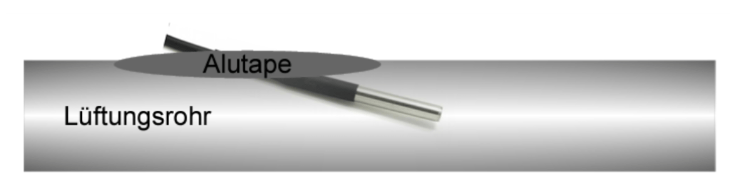
The shipped cables comes with this sensors or can be ordered in the shop. To measure the outside temperature, the sensor is to be placed e.g. in the front vent.
This can also be done in the ventilation pipe if available. In this case, a small slit is cut with a cutter knife, the temperature sensor is pushed in and sealed with aluminum adhesive tape or silicone, for example.
Speed to Fly switch:
The vario/speed command switch is to be connected to pin 4 of the RJ45 and to ground pin 8. If the switch is closed, target travel is selected. The function can also be changed in the setup, i.e. when the switch is closed, Vario mode is selected.
S1 Serial (FLARM plug)

The FLARM is the standard configuration for the Interface S1 and can be connected to the XCVario with the standard FLARM cable at FLARM plug labeled ending. With the simple FLARM cable, only the direction FLARM is connected to XCVario (Series 20), i.e. only pin 4 in FCC numbering. These cables are no longer offered. The bidirectional FLARM cable is required for bidirectional communication with the FLARM (standard from series 2021). This enables e.g. the flight declaration in FLARM via the navigation system (e.g. XCSoar).
Below is the assignment at the FLARM end of the standard cable, the minimum connections required for receiving FLARM data are shown in bold.
| Pin# RJ45 FCC | XCVario FLARM Cable End | FLARM with RJ45 Interface |
| 1 | GND (orange/white) | GND |
| 2 | GND | |
| 3 | RS232 TX (green/white) | RS232 RX |
| 4 | RS232 RX (blue) | RS232 TX |
| 5 | ||
| 6 | ||
| 7 | +8..28 VDC | |
| 8 | +8..28 VDC | +8..28 VDC |
RJ45 connector S2
The hardware has the second electrical RJ45 connector “S2” with standard IGC pins for the serial port, plus an additional input/output for a flap sensor and for a CAN bus (2). It is recommended to use the S2 extender to connect various gadgets to the S2 connector. A single gadget such as a CAN Magnet-Sensor, a second XCVario or a flap sensor can be connected directly.
Interface S2
| FCC Pinout RJ45 | Identifier | Direction | 568A | 568B | Connection |
| 1 | GND | Power In | grün-weiss | orange-White | Bordnetz Masse |
| 2 | GND (1) | Power In | grün | orange | – |
| 3 | RS232 TTL TX | Signal Out | orange-weiß | green white | Navi Serial RX |
| 4 | RS232 TTL RX | Signal In | blau | blue | Navi Serial TX |
| 5 | CAN-L (2) | Signal Out | blau-weiß | blue White | – |
| 6 | analog input | Signal In | orange | green | 0 ..1.2 volt voltage against GND |
| 7 | CAN-H (2) | Signal Out | braun-weiß | brown-white | – |
| 8 | +8..28 V | Power In | braun | braun | electrical system +12V DC maximum 500 mA power output |
(2) From series 2021/3 available since October 20211
S2 Serial (Device)
Standard configuration for S2 is a serial device such as Kobo, serial OpenVario, a radio or else. The Pins are according to the IGC standard, hence a 1:1 cable is only recommended for devices that do not have any connection on the other pin’s except GND and on power pin. Other devices shall be connected via the S2 Extender/Splitter that only connects the serial pins, power and GND.
Analog Input (flap sensor)
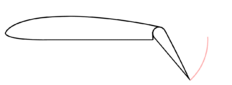
Any XCVario with an S2 interface features an analog input for various functions. The major application of this input is usage with the flap sensor. Its also usable as a gear alarm input alternatively (see gear warning chapter).
The flap sensor is available in the shop, and is to be mounted in a suitable position near the flap linkage and must be fixed to the fuselage wall with an appropriate holder e.g. with 5-minute epoxy, and attached to the flap in order to get a rotation of the shaft by an adhesive joint on the flap linkage. Under no circumstances should the linkage be drilled into.
Note: The analog input can only be used in Bluetooth mode due to a limitation in the first series 2021. For applications that require WiFi mode, the hardware will be required from March 2021.
CAN Bus

The XCVario-22 hardware features a CAN bus interface as an option for data transmission to a second device and to connect additional hardware such as the CAN magnet sensor.
External Devices
OpenVario
The OpenVario (including the Stefly OpenVario) can be connected directly to the XCVario via ttyS1 or ttyS2 using either a 1:1 cable at S2 or the standard FLARM cable at S1. In this configuration, the XCVario receives its data directly from the OpenVario.
Power considerations:
- Supplying power from the XCVario to the OpenVario is not recommended, due to the OpenVario’s larger display and higher power consumption. It is better to let the OpenVario act as the power source.
- In this setup, the XCVario’s power input at connector S1 remains unused.
- If you prefer to power the devices separately—for example, to switch them off individually in a power shortage or to protect each device with its own fuse—you must disconnect the +12 V line in the patch cable and supply the XCVario independently at S1.
Alternative connection via ttyS0 on the OpenVario:
- Connect the RX, TX, and GND pins from the OpenVario Sub-D connector to the serial interface of the XCVario at S1 or S2.
- On the variometer, set RX/TX pins to “Swapped” under … Navi → S[1|2] serial → Swap RX/TX. The default is Normal.
- Ensure the baud rate matches on both devices. All other serial interface settings remain unchanged.
FLARM integration:
- The FLARM can be plugged directly into the OpenVario, or forwarded via the XCVario.
- All routing requiers no configuration and is done automatically.
- The pins shown in bold represent the minimum required connections to display FLARM data on the OpenVario.
| FCC Pinout RJ45 | IGC Pinout RJ45 | XCVario S1 FLARM or S2 | OV ttyS1 ( o. ttyS2) |
| 1 | 8 | GND | GND |
| 2 | 7 | NC | GND |
| 3 | 6 | RS232 TTL RX | OV TX |
| 4 | 5 | RS232 TTL TX | OV RX |
| 5 | 4 | – | – |
| 6 | 3 | – | – |
| 7 | 2 | – | +8..16 VDC |
| 8 | 1 | +8..16 V | +8..16 VDC |
- For connecting to the OpenVario (OV), XCVario recommends using a standard RJ45 (8P8C) cable, i.e., 8 pins with 8 connections, wired 1:1, as commonly used in network technology. You can search for a flexible network cable on Google or Amazon.
- Typically, a 0.5 m cable is sufficient between the two devices on the instrument panel.
Important notes for wiring:
- When connecting an XCVario-22 to the OV, the S2 splitter is always required. This is because the OV also supplies +12 V on pin 7, and connecting directly could damage the CAN bus (no guarantee if an OV is connected directly to S2). The OV should be connected to the RS232 splitter port.
- If the +12 V supply to the OV should be completely suppressed, insert the Y-piece and remove both jumpers for pins 7 and 8. This ensures only the data connection is established between the two devices.
Double-seater configuration (two XCVarios and two OVs):
- The cables only need to be connected to the front device. Data from the front device can be forwarded to the rear device via the CAN bus.
- Connect the splitter to S2 on the front device. The patch cable from the front device to the splitter should not exceed 50 cm; shorter cables reduce the risk of interference.
- The rear device can then be connected to the CAN port of the splitter via S2 using a patch cable of suitable length. In this setup, the rear device is powered via the patch cable from the front device, so no separate power wiring is needed.
Cable and sensor considerations:
- Using an additional 1:1 RJ45 Y-piece on the CAN bus after the splitter, a CAN magnetic sensor can also be integrated.
- Use flexible cables to prevent stress on the plugs. Keep them as short as necessary.
- Additional sensors (e.g., flap sensors) can be connected to the splitter.
KRT2
XCVario Interface Setup
The connection to the radio of the type KRT2 makes sense if your navigation device has a driver for it (XCSoar and LK8000 do so), can be established by a serial connection with any XCVario model that features a S2 interface on its back (all do except XCVario 20). The baud rate should be set to 9600 baud (the only one KRT2 supports).
Attention: To enable the “Navi” you are useing to benefit from the attached KRT2 you have to configure a peer device called Radio remote. configure the Radio remote to the same interface as the Navi and thus protocol and routing will be enabled to control the KRT2.
Wiring KRT2
To connect the serial interface of your KRT2 make the connection from S2 pin 3 and 4 to the corresponding serial RX/TX of the KRT2, it is best to solder it there to the existing KRT2 Sub-D connector, to pin 2 and 13, crossed, i.e. RX from vario to TX of radio and vice versa as follows:
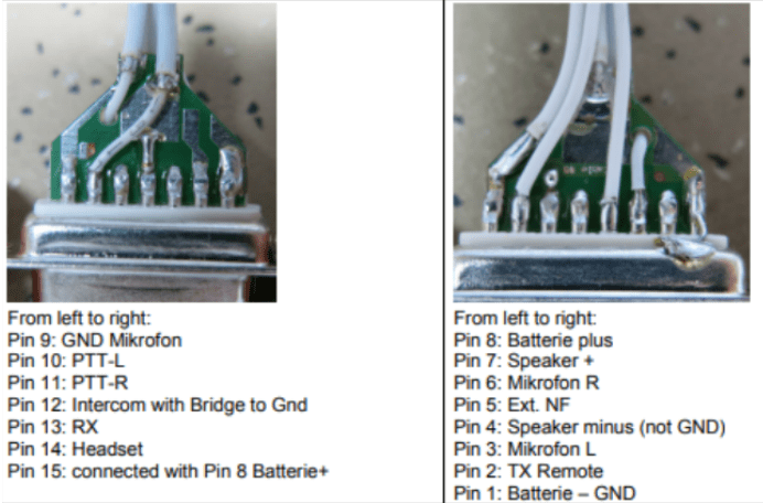
XCV 3 (TX)  <-> 13 KRT2 (RX)
XCV 4 (RX)  <->  2 KRT2 (TX Remote)
XCV 1 (GND) <->  1 KRT2 (GND)
The software connection with the XCVario is only possible in WiFi mode (which may have a few disadvantages, see the Wireless LAN manual), via the TCP client with port 8882. Configure the driver for the KRT2 in the navigation system there.
Unfortunately, a connection via Bluetooth is not possible aside of XCVario because XCSoar can only configure one driver for an interface and only one Bluetooth connection to a device is possible. Alternatively, to stay with Bluetooth, there is the option of connecting the KRT2 to the XCSoar as a separate BT device via an external Bluetooth bridge. BT bridges are available from many manufacturers, or here in the shop: https://xcvario.com/product/serial-bluetooth-WiFi-adapter/
Using External Audio from KRT2

The XCVario has a highly efficient digital amplifier with pulse-width modulation that does not relate directly to ground, but rather emits a symmetrical signal (2). If you connect both poles of the audio out to the asymmetrical KRT2 radio input, one output suffers a short circuit to ground, what even can cause damage of the audio driver stage in prolonged operation, and high frequent noise. Do also not try to connect just one pin, and leave the other open, there will be noise as this is an invitation for disruptions: a ground loop across the supply lines. To get from a symmetrical output to an asymmetrical input, a small audio isolation transformer helps, which is available in small format for little money, for example here: https://www.ebay.de/itm/394922853247. Or here with cable ends: https://www.thomann.de/de/neutrik_nte_4_audio_uebertrager.htm . One side of the transformer is then connected to the two lines of the jack on the XCVario, e.g. on the Neutrik Yellow/White and the other side is between pin 5 and GND on the KRT2 (red/black).
ATR 833 Radio
The pin assignments and connections on the ATR833 are as follows, the corresponding driver is labeled ATR833 in XCSoar.
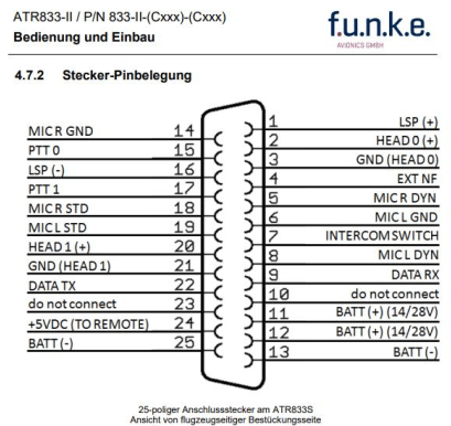
XCV 3 green/white (TX)   <->  9  ATR833 (Data RX)
XCV 4 blue (RX)          <-> 22  ATR 833 (Data TX)
XCV 1 orange/white (GND) <-> 25  ATR 833 (GND)
ECW100 (Flarm/GPS)
The ECW100 Flarm might be connected to the FLARM labled plug ending at S1 cable tree to the PC labled connector at ECW100. If a driver is needed for flight upload, FLARM is to be selected. For the GPS data there no driver required, GPS is standard NMEA and processed be XCSoar in any case. The connections are as follows:

PC (RS-232) D-Sub 9 (f)
XCV 3 green/white (TX)  <-> 11  ECW100 (RX)        (3 PC RS232)
XCV 4 blue (RX)          <-> 12  ECW100 (TX)        (2 PC RS232)
XCV 1 orange/white (GND) <-> 13  ECW 100 (GND)    (5 PC RS232)
Source: Installationshandbuch ECW100 V1.6 pdf
Power Supply
The power supply is connected to the vehicle electrical system. A single fuse for a variometer is not mandatory for gliders, but is recommended. The wiring can be done with copper strands from 0.14 mm², 0.25 mm² is recommended. Alternatively, the XCVario can be connected in parallel to another device that is fused with at least 0.5, better 1 ampere. The device must be protected because the plug and cable are not designed for higher currents. The device tolerates voltages in the range of 5-28 volts, a supply of 12 volts is ideal. If the device is operated without any protection plus an external short circuit, e.g. at S2, internal damage is to be expected which is not covered by the guarantee. It is therefore essential to also secure it on the laboratory bench for test purposes.
The XCVario is protected against polarity reversal and is internally protected against transient overvoltages such as ESD discharges and induction peaks when starting. In general, the avionics should be left switched off when starting, if it cannot be avoided, e.g. when starting during the flight, you have to rely on the overvoltage protection.
Vario / Speed to Fly Switch
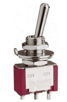
The vario S2F switch can be attached to the stick or in the instrument panel. Its second pin must be connected to ground (negative pole supply). With ground contact at pin 4, the vario is in speed to fly mode, with an open switch in vario mode. The speed command display is constantly in operation, but the tone generator changes to speed command as input. A button can also be used instead of a switch. In this case, the switch type must be set accordingly in the setup.
The switch is not absolutely necessary, as it is possible to automatically switch over to S2F from a certain speed. This can be achieved in the Audio/AudioMode menu with the “Autospeed” setting. The “AutoSpeed” is the speed above which the variometer switches to the S2F mode.
Serial RS232 Connections
The RS232 interface’s at the connectors S1 and S2 are used to connect a device without wireless (Bluetooth or WiFi) support, e.g. legacy OpenVario, older Kobo, or to connect a serial FLARM IGC port to the XCVario.
With a bidirectional cable (RX and TX direction connected), a flight task can also be declared in FLARM, the FLARM can be managed from your Navi App, or a flight download can be carried out. For the cable, see the description in the chapter on cable assembly. The FLARM application is preset, no settings need to be made on the serial interface in the setup.
In principle, only one device can be connected to one serial interface port. This is a limitation coming from the RS232 protocol. Analogy: One teacher can talk to multiple students at the same time, but only one student may as a question. There are tricks to connect multiple devices to one RS232 port, e.g. the second device does not have wired the transmission direction (TX) towards its peer, it can be connected in parallel. This may require special cables or adapters which not all have connections and do not connect the TX wire from the peer.
In the case of an OpenVario on the serial interface, the “XCVario” data is needed on the serial interface, which can be set in the setup of the “RS232 Interface S1” under “TX Routing”. More information in the setup description.
Pinout in IGC- and FCC Standard’s
The RJ45 socket pins in this document are numbered according to the international FCC standard, which is the numbering convention most commonly used worldwide. In contrast, the IGC (International Gliding Commission) standard for logger interfaces uses a reversed pin numbering scheme.
The XCVario S2 interface and the S1 FLARM plug follow the IGC standard exactly.
In this document, the primary pin numbers are given according to the FCC standard, while the corresponding IGC pin numbers are optionally shown in an additional column for comparison.
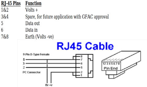
The left figure shows the FCC standard, in which the first pin is identified as pin 8 when viewing the RJ45 plug from the front.
The figure on the right shows the IGC standard with reversed pin numbering (source: Technical Specification for IGC-approved GNSS Flight Recorders – Second Edition with Amendment 6, 25 November 2020). In this case, numbering starts on the left-hand side of the connector with pin 1.
When checking the pin assignment of a device, it is essential to always verify the pin numbers against the corresponding diagram and viewing direction. According to the IGC standard, the numbering of the RJ45 plug (right) is correct. However, the numbering of the RJ45 socket (left) is incorrect. The table applies only to the plug as viewed from the front, with the cable pointing away from the observer, and is therefore not valid for the socket.
This can easily be verified: if the RJ45 plug shown were inserted into the corresponding socket, pin 8 of the plug would mate with pin 1 of the socket, which is clearly incorrect.
In summary, the plug is numbered correctly, while the socket is numbered incorrectly; the pins on the underside of the socket should be labeled 7 and 8.
Comparison of the pin numbers of the FCC and the (wrong) IGC standard:
| Signal | RJ45 FCC Standard Pin# & IGC Standard Plug Pin# (right) | RJ45 IGC Socket false Pin# |
| Volts + | 7+8 | 1+2 |
| Data out (TX) | 4 | 5 |
| Data in (RX) | 3 | 6 |
| Earth (GND) | 1+2 | 7+8 |
Installation and drilling plan
Mechanical Installation Specifications
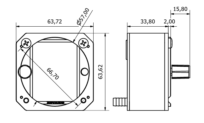
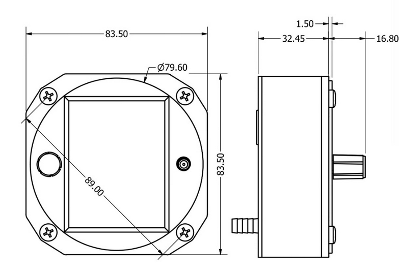
The 57 mm variant (left) conforms to the standard aviation cutout for 57 mm instruments. The 80 mm variant corresponds to the standard mounting dimensions for 80 mm panel instruments. Mounting is performed using four M4 screws. The panel holes should be drilled to a minimum diameter of 4.5 mm.
⚠️ Important: The mounting screws must not penetrate more than 10 mm into the device housing. Exceeding this limit may damage internal components, and proper operation cannot be guaranteed.
Recommended screw lengths for a panel thickness between 1 and 3 mm is M4 × 10 mm.
Mounting hole circle diameters:
80 mm device: 89.1 mm
57 mm device: 66.7 mm
In the case of particularly thick instrument panels with a thickness of more than 2 mm, a small, preferably semi-circular niche with a width of 2 mm and a height of 14 mm must be created halfway up the side for the rotary button. Normally this is not necessary, since standard panels are approx. 2 mm thick.

The 57mm device was developed for a 57mm bore and is optimally adapted for it. The 80mm device is more suitable for an 80 mm cut-out.
The installation of the 57 mm device in an 80 mm cut-out is possible using our cover as below.
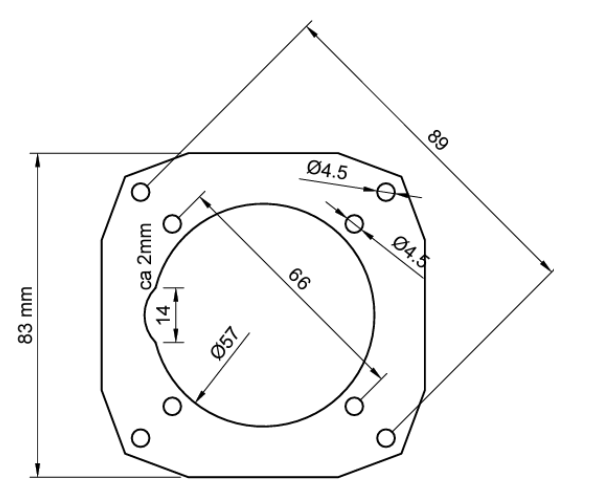
Drawing of the front part
The exact dimensions of the front part as interface to the instrument panel is shown below. The device is fully symmetrical and can be mounted TopDown im case the rotary button is preferred on the right side.