
DISPLAY
Orientation

[NORMAL]
[TOPDOWN]
By default, the variometer display is configured upright with the rotary knob on the left side. In case it suits you better to have the rotary knob on the right side of the display, choose the [TOPDOWN] orientation. An experimental [NINETY], for a 90° degree mount with the button underneath the display is available in expert mode.
Pixel Test
[Cancel]
[Start]
The display test shows a fully white screen as well as a fully black screen in sequence, in order to detect faulty pixels.
Rotary Knob
Sensitivity

1 Indent
2 Indent
This setting allows adjustment of the rotary switch sensitivity. Some rotary switches generate two pulses per detent; in such cases, the display shows “2–4 indents per increment” to prevent skipping values. The optimal sensitivity is configured at the factory and typically does not need to be changed. The default setting of 1 indent per increment is recommended.
Enter Setup by

[Short-Press]
[Long-Press]
This setting allows you to select whether the XCVario opens the setup menu exclusively on a long button-press. By default the short press cycles through all configured screens with the setup screen as last in the list of screens. If you prefer the quick access of the setup menu using the long press from any screen select [Long-Press], leaving the short press reserved for screen navigation.
Speaker
[Enable]
[Disable]
Option to disable the audio amplifier. It does drop the power consumption a bit, e.g. for a two seater setup. Pressing the button on [Enable] starts a sound check melody.
Flap Sensor
Flap Sensor
[Disable]
[Enable]
Configure the XCVario flap sensor here after connecting the hardware to your device.
Sensor Calibration
[Cancel]
[Start]
Starting the sensor calibration will guide you through all configured flap positions of your glider.
Gear Warning
[Disable]
[S2 Flap positive]
[S2 RS232 positive]
[S2 Flap negative]
[S2 RS232 negative]
[External]
With the “Gear-Warning” a warning can be triggered in the case of extended brake flaps and retracted landing gear. The magnetic contact on the brake flap must be closed when it is retracted, and the contact on the landing gear when it is fully extended.
Note: The warning can be acknowledged by pressing the rotary and then turns off for 500 seconds or about 8 minutes.
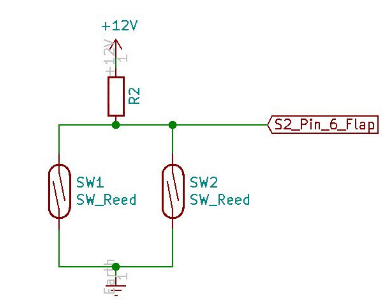
Both contacts are switched in parallel with one end connected to ground (GND, battery minus) and the other end connected to pin 6, the flap sensor input, to S2 and connected to +12 volts via a pull-up resistor. Alternatively, pin 4 on S2, the RX pin of the RS232 interface, can be used, and there is an option for external [External] commands that can be send by an external device in order to trigger the gear warning, see the „$g“ commands section for details about this.
The warning is given optically with a textual display "Check GEAR" in the popup text field, and there is an audible warning tone, and has priority over the other displays, with the exception of the stall warning.
The feature is available if either the flap sensor or the RS232 interface on S2 is not configured, i.e. setting: Disable is mandatory there and is switched off by default, or if you don’t use the flap sensor input.
The switching of the two magnet contacts is shown on the right, both must be designed as normally open contacts, i.e. they must be shot in the vicinity of the magnet. The pull-up resistor R2 is necessary for a high-level and should be in the 100 to 150 Kilo-Ohm range and at least 1/8 watt of power.
With the “negative” options you can also use contacts, which are to be laid in series and then close when the flaps are not locked, or the landing gear is not fully locked. The last option “Extenal” means the gear warning information is received by XCVario protocol via any supported interface.
Airspeed
AS Calibration
0 %
With the AS Calibration, a proportional calibration of the airspeed can be carried out. The calibration can be set in 1% steps in the range of +-10%. For example, with a calibration of +5%, instead of 100, 105 km/h will be displayed. This is normally not necessary, as the accuracy of the sensor is usually completely sufficient, however, the pressure readings in the aircraft can run incorrect values, and so there is an option here to minimize these errors. Default is 0% calibration. The AS calibration calibrates the respective value according to the setting IAS/TAS.
Set Zero

[Cancel]
[Now]
With this option, the zero point of the airspeed sensor can be re-calibrated. The high accuracy of the airspeed sensor is ensured by a daily calibration of the zero point. This is normally carried out automatically on the ground when the power is turned on and is therefore only necessary in exceptional cases. At low speeds < 30km/h, very low pressures are relevant, different wind pressures from a gust or the propeller on the statics or the pitot tube when switching on can possibly lead to a deviation. If the display on the ground does not show exactly zero due to an incorrect zero point, this can be a remedy.
Swapped Tubes
[Straight]
[Swapped]
Some older HW types have AS sensors with tubes swapped, in case there is no airspeed reading, the option [Swapped] will correct for this. This configuration option is only visible for XCVario hardware that has those differences.
IMU & AHRS

All XCVario devices from the 2021 series onward feature a 6-axis Attitude & Heading Reference System (AHRS) or IMU sensor chip, which includes accelerometers for all three axes and gyroscopes measuring rotational speed in all three axes.
The sensor is used to record acceleration or load factor (G-load), for example during circling, which effectively acts like additional ballast by increasing optimal glide performance. It also provides data for the artificial horizon and supplies load factor information to XCSoar.
Temp Control
45 °C
The AHRS chip temperature can be regulated to a constant setpoint by an internal heating. A stable working point improves G-meter and gyro accuracy, resulting in a more accurate artificial horizon. The default setpoint is 45 °C. It may be adjusted for different climates. Setting the value to –1 °C disables this function.
A temperature rise of about 35 °C above ambient is possible, providing stable regulation at a 45 °C setpoint over ambient temperatures in cockpit of roughly from 10 °C to 45 °C.
AHRS RPYL

[Disable]
[Enable]
This function can be used to activate a data stream generated by a Levil AHRS. It produces $RPYL and $APENV1 data records, which include AHRS information such as pitch, roll, and yaw (if a magnetic sensor is installed), vertical load factor (Z-direction), altitude, airspeed, and TE variometer data.
The feature is disabled by default and is only required for programs that support it. Its primary purpose is to enable applications such as a sky map, which is currently under testing.
AHRS RAW
[Disable]
[Enable]
Option to send as well the RAW AHRS gyro and accelerator data the follwing format.
!XCV,
G,<gx>,<gy>,<gz>, // gyro rotation deg/s
A,<ax>,<ay>,<az> // acceleration in multiple of G
*CRC // standard NMEA checksum
<CR><LF>
Battery Meter
Battery Type
[Cancel]
[LeadAcid]
[LiFePo4]
The battery type must be configured to align the battery meter with the voltage characteristics of the battery installed in your glider. Four reference voltages are defined for each battery type, representing the range from empty to full. Selecting a battery type presets these voltages according to the chosen type. Each voltage can also be adjusted individually if needed to match your specific battery.
Voltage definitions
Empty:  11.50 Volt
Critical: 11.75 Volt
Moderate: 12.00 Volt
Full:     12.8 Volt
Voltmeter Adjust
-0.00 %

12.75 Volt
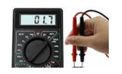
This dialogue is intended for factory use only to precisely fine-tune the battery voltage measurement for maximum accuracy. At factory the voltmeter is calibrated. Without this adjustment, voltage measurement accuracy is approximately ±1%. Performing the calibration requires a multimeter to measure the voltage exactly an the cable ends where the variometer is connected.


