
Wait a couple of seconds until translation has finished until last page, then press print button to print or create a pdf file from latest XCVario documentation
Inhaltsverzeichnis
- 1. Introduction
- 2. Features
- 3. Overview
- 4. Operation
- 5. Device Management
- 6. FLARM
- 7. Configurations and Router
- 8. Basic Setup
- 9. Vario and Speed 2 Fly
- 10. Audio
- 11. Glider Details
- 12. Options
- 13. Units
- 14. Flap (WK) Indicator
- 15. FLARM
- 16. Compass/Wind
- 17. Wireless
- 18. G-Load Display
- 19. System
- 20. Software Update
- 21. Battery Setup
- 22. Hardware Setup
- 23. Altimeter, Airspeed
- 24. Serial Interfaces
- 25. NMEA Protcols
- 26. Logging
- 27. XCSoar
- 28. Installation
- 29. Technical Specification
- 30. Maintenance
- 31. Warranty Policy
- 32. Permit
- 33. Limitation of Liability
Introduction
XCVario User Manual
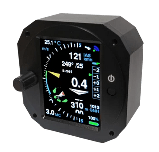
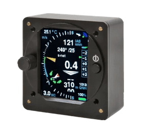
XCVario 57mm and 80mm
Series: All
Software Version: Latest
Manual edition 3.04
info@xcvario.de
Other versions of earlier software statuses at: https://github.com/iltis42/XCVario/tree/master/handbook
General
The XCVario is a modern digital and smart variometer with wired serial and wireless interfaces to any navigation display or with applications such as XCSoar, LK8000 and more, as well as wired interfaces to a GPS source, a FLARM, an OpenVario or other devices. It has modern, high-resolution digital sensors for pressure, acceleration and temperature, an expansion tank as is usual with older systems is no longer required.
The XCVario is connected to the TE nozzle pressure, the static and the dynamic pressure, and compensated either conventionally via the TE nozzle or electronically. It has an audio function via its own built-in 2 watt speaker.
The forward-thinking Kalman filter offers a quick response to changes with good smoothing of the vario display, without the usual delay of a few seconds, which is known from simple damping. The Vario shows exactly what you feel. The Vario can also be adjusted according to personal preferences via the setup with many setting options.
From the 2021 series, the load factor (n) is taken into account when calculating the current sink value from the polar coefficient using an acceleration sensor, because the increased load factor requires more lift from the profile with the same aircraft mass (difference to higher ballast). This increases the drag coefficient and this leads to increased sink rates. In a standard class aircraft, for example, with a load factor of 2 g, this results in about twice the sink rate. This is not insignificant and is taken into account in the net vario, which significantly improves the net vario display, especially in the case of dynamic processes (pull up, push down) compared to conventional devices without the corresponding sensors.
Optionally, a FLARM or another source for NMEA (GPS) data can be connected to the XCVario, the Vario not only forwards this data to XCSoar, tasks can also be declared on an (IGC) FLARM with XCSoar, settings made and the flight can then be read out. Clubs can operate the device with its many options in the “Student Mode”, which allows users to only modify the 5 most important settings such as QNH, MC, etc.
The standard installed and freely available software of the XCVario (https://github.com/iltis42/XCVario) offers many features. In addition to a vario display, speed with MacCready setting, there is a precise altimeter, a wind indicator, a charge level indicator for the battery, a temperature indicator and more. The flap display, which can be switched on as an option, can display the flap position using an external sensor and provides information on the optimal flap position depending on the wing loading, the speed and the load factor. Thanks to a growing library of more than 100 polars for a wide variety of glider types, the vario can be adapted to almost any glider. Since the software is publicly available on github, developers can clone the software and further develop their own features and ideas, and also deliver them.
In addition to the independent function, the Vario can exchange data with the software running there via the wireless interface either via Bluetooth or wireless LAN (WLAN, WiFi), or via the RS232 (-TTL) interface, depending on which interface the device used has . The wireless standards ensure secure and stable transmission and have the advantage that there is no need for hardware-related and sometimes complex cabling with the navigation device.
Thanks to the high resolution of the digital, temperature-compensated and factory-calibrated pressure sensors, even the smallest height differences of just 8 cm are detected. Properties such as accuracy, reliability and long-term stability are therefore given. The sensor for the dynamic pressure or speed or IAS enables an absolute accuracy of better than 1%, at 100 km/h the deviation is a maximum of 1 km/h.
The outside temperature can be measured with the digital temperature sensor in the ventilation area to 0.5° Celsius with a resolution of 0.1° Celsius, and is included in the calculation of the TAS (True Airspeed) as an atmospheric parameter for determining the air density.
The exact flight speed, as well as the temperature and TE vario values, can be used to calculate precise values for the target flight. The precise altimeter without hysteresis allows final approach altitudes to be calculated appropriately in XCSoar, because the wind calculation in XCSoar and now also in the XCVario itself works reliably and precisely together with a GPS source.
It is very easy to operate and is done using the rotary (rotary knob) with Push&Turn (press and turn), next to it there is a button to switch it on. The system, which is manufactured in large numbers, is an excellent replacement for old vario systems with many additional modern features.
Features
- Airliner-style bar display or retro-style pointer display
- TE variometer with optimized Kalman filter, adjustable range and damping
- Barometric altimeter with QNH setting or QNH autosetup (airfield altitude as default)
- Speed display (IAS or TAS) with speed command (S2F)
- Adjustable wing loading and MacCready value
- Built-in speaker with volume control, power 3 watts
- Sound individually configurable (height, chopping, dual tone, deadband
- Flaps display with optimal position according to ballast, airspeed and the load factor
- Extensive polar library with over 100 common polars
- Polar can be modified later
- Digital compass with external magnetic sensor (21 series)
- Wind calculation in circular flight and with compass also straight flight (TAWK method, in development)
- MacCready, ballast and bugs setting option
- stall warning
- Outside temperature display with external sensor
- Battery charge status display, voltages configurable
- Wireless Bluetooth V4.2 (classic BT) or standard WLAN access point for external devices
- 2x RS232 TTL interfaces, S1 with standard cable in IGC standard, S2 socket in IGC standard
- High accuracy barometric altimeter
- Sunlight readable, bright and high-contrast 2.4 inch IPS display with 57 mm diagonal
- Switch input for vario/set speed changeover (switch or button adjustable)
- Simple setup menu using rotary switch with push and turn function
- Light and small device avail for standard 57 mm instrument cut-outs, housing depth only 35 mm
- Elegant and robust CNC milled mat black anodized aluminum housing (shielding, low EMI)
- Software update via WiFi ‘Over The Air’ (OTA) when installed for new feature
- Analog input for flap display
- As an alternative to the flap display, landing gear warning via the same input
- Full FLARM Bridge for task declaration in IGC Flarm, flight download and FLARM setup
From the hardware 2021 series, the following 3 new hardware features have been added:
- Audio power now 2 watts, better sound at high volumes
- Second serial RS232 TTL interface S2, IGC standard assignment and DTE and DCE support (RX/TX pins exchangeable via software)
- Input e.g. for a flap sensor or an undercarriage warning
- Optional feature: Attitude and Heading Reference System (AHRS): 6-axis direction and attitude sensor with 3-axis gyroscope and 3-axis accelerometer
From hardware series 2022:
- In addition, a CAN bus interface on S2 for connecting a second two seater device, a CAN magnet sensor (from October 2022), as well as future extensions.
From hardware series 2023:
- Temperature control for the AHRS chip for improved long-term stability
Overview
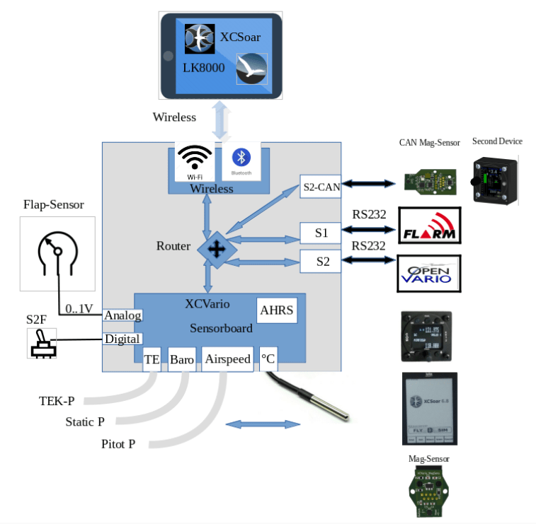
The following overview shows the embedding of the XCVario in the cockpit environment.
The standard case and most common case is the connection of an Android device with XCSoar to the wireless interface with Bluetooth, as well as a FLARM with the appropriate cable to interface S1.
For this purpose, the interface S1 is connected to the wireless interface. This is the delivery state of the settings.
With the WiFi standard on the wireless interface, it is also possible with devices from the 2021 series to control another device, e.g. a radio device on the S2 interface. More on this in the XCSoar Setup chapter.
Operation
The operation of the XCVario is very simple and intuitive, and takes place via a rotary knob (rotary) with button function (push and turn), an optional additional switch or button (configurable) for Vario or speed command mode, and via the on-off switch. The following description applies to the default setting, the function of the rotary can be set, more on this in the chapter on setup.
After switching on on the ground, the QNH must first be set on the rotary knob, or confirmed if the elevation (height of the airfield) is configured. After pressing the rotary knob, the display and the data transmission of the device go into operation. Turning it to the left decreases the volume, while turning it to the right increases it.
During operation, the menu for the parameters such as MC value, ballast, polar and more is started after pressing a button (push).
A simple push takes you to the top point of the setup [<<Setup], which offers a return from the setup without turning, i.e. scrolling in the menu. Another push without scrolling switches back and forth between setup and normal operation. In the setup menu there is a help text for almost all functions so that the correct settings can be found quickly even with little practice.
By turning the rotary to the right, corresponding to “scroll down”, or to the left for “scroll up”, the individual sub-items are selected in the setup.
Most of the items in the setup menu return to the top item of the previous level, allowing multiple settings to be made without exiting the menu entirely.
The setup menu is nested, you can descend further into the individual items by pressing a button (push), the top item returns to the previous menu.
All setting values can be decreased by turning to the left and increased by turning to the right.
If you want to save the value, you can acknowledge this with a simple push, the saving is confirmed and you return from the dialog.
Dialogs for parameters that are usually set separately, such as the MC value, return directly to the vario display. This saves you having to press another button to exit the setup.
The XCVario can also be remotely controlled via software commands, supported is rotary operation such as short or long press to change the screen, for example, or to go to the setup, scrolling (up/down) for the menu navigation, as well as some shortcuts for changes in volume or MacCready value.
Device Management
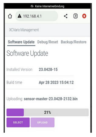
An important feature is the XCVario management via the WiFi access point of the device. After activating the “ESP32 OTA” WiFi, e.g. by pressing a button when switching on immediately when the line with the software version appears, the adjacent management page can be called up via a WiFi-enabled device via the page https://192.168.4.1. Below that you can find the software update, under Debug/Reset a factory reset (see the separate chapter under “Setup”), a possible core file for debugging purposes, and under Backup/Restore a backup file of the configuration on the mobile phone , tablet or laptop and import it back to the device.
Software Update
Under the Software Update tab, the installed software version is displayed, as well as other details such as the exact time when the package was built. Using [SELECT], the file with the new software can be selected on the smartphone and then uploaded via [UPLOAD].
Debug/Reset
The operation is self-explanatory, after pressing the [FACTORY RESET] button, the execution must be confirmed in another dialog, the device is then reset to the factory settings. This means that all settings are lost unless there is a backup of the configuration (next point).
The [DOWNLOAD CORE DUMP] button provides a file that can be sent to the manufacturer for troubleshooting if the device shows malfunctions during operation, e.g. with new features that are still running in alpha mode, i.e. in test mode. The core file is only created if the system encounters a fatal error and the software restarts, and is deleted after uploading to the XCVario.
Backup/Restore
Here, too, the operation is self-explanatory, [BACKUP] writes all settings that deviate from the default, including the calibration of the compass, or a deviation table in a file which can be stored on the mobile phone, tablet or PC.
On the other hand, [RESTORE] loads the configuration from the file back into the device, which is very helpful, for example, when replacing a device or upgrading to a newer model or after a factory reset has been carried out. Basically, no factory reset is carried out during the restore, i.e. other settings that are not in the backup file are initially retained. If you only want to see these settings from the backup file, then a factory reset must be carried out beforehand. This means that, in addition to a clean restoration of an earlier status, there is also the possibility of a “merge” of the existing configuration with the status from the backup.
FLARM

Every FLARM, whether classic, power or RedBox FLARM with RJ45 connection can be connected to the XCVario with standard cables. The cable available in the shop has the power option, with which the FLARM is also supplied via this cable. This saves additional wiring for the supply of the FLARM from the vehicle electrical system. Other FLARMs with RJ12 connector or Sub-D connector can also be connected with a modified cable.
If the FLARM is plugged in, the NMEA data from the GPS and barometric probe (if the FLARM is available) are sent to XCSoar with the FLARM cable as standard. With the bidirectional FLARM cable (see chapter Electrical connection /FLARM), tasks can also be written to an IGC-Flarm and settings of the FLARM can be made. See the description of XCSoar.
A flight download can also be carried out with the recorded flights in FLARM. To do this, the FLARM must be created as a separate device with the “FLARM” driver in XCSoar and activated for the download (Config/NMEA Connection/FLARM../Activate). During activation of the FLARM driver, other drivers such as OpenVario, which use the same Bluetooth connection, must be deactivated (Config/NMEA connection/OpenVario../Deactivate). The flight download can then be tapped in the FLARM device, a list of flights is first transmitted, from which the desired flight is then selected. The flight download via the serial interface can take a few minutes, depending on the length of the flight, since the data rate of the serial interface at the standard 19,200 baud only allows around 2 kilobytes per second. Higher data rates for faster downloading are possible, see the chapter on setting the baud rate of the serial RS232 interface. If XCSoar is connected via WiFi instead of Bluetooth, the FLARM can also be created as a separate device in XCSoar with the “FLARM” driver. It is then no longer necessary to create (or change) the device driver for the flight download or to switch to the Vario Setup menu. The flight download via the WiFi interface is possible with a WiFi device, which is connected via the Flarm port for the purpose. Other devices connected to the XCVario must be switched off during the download.
In the current software versions, there is also a simple FLARM screen to warn of an imminent collision with another aircraft, which graphically visualizes the distance, direction and height offset of the approach. Depending on the alarm level, an acoustic warning signal with an adjustable volume is also used to draw attention to the danger.
Configurations and Router
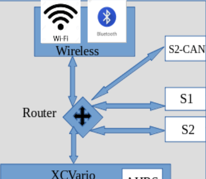
An important functionality of the XCVario is the integrated router function, which makes it possible to connect the data of the device and data from external devices between the various interfaces of the device. This results in a multitude of possibilities for using the XCVario and thus almost any extensions and possible uses are covered. An overview of this follows, further setups are conceivable and can be derived from the combinations shown.
It is generally recommended to switch off connections that are not required, as they unnecessarily occupy resources such as CPU and RAM, especially if there is no destination at the other end, the data accumulates, cannot be delivered and must be discarded. With a minimum setting for the routing, the full performance for the Vario operation of the device is available.
The routing of data that is sent to the XCVario from outside via any interface is always activated, i.e. the XCVario always reacts to FLARM and GPS data, commands, etc. without having to program a routing for this. For the XCVario data itself, i.e. the outward direction, the routing must be set accordingly for the interface. The XCVario data is also automatically routed to the CAN bus in the CAN mode master.
Configurations that require the CAN bus can therefore only be used from the current hardware series XCVario-22.
The configuration of the router is always bidirectional, i.e. both the forward direction and the reverse direction of the data streams are always connected.
Any of these ports can only ever be connected to one target bidirectionally. To setup the routing, see the “Routing” description in the setup chapter for the corresponding ports. The reverse direction is automatically configured, for example if we enable S1-RS232 as a target in the wireless interface routing settings, then at the S1-RS232 interface, the Wireless is enabled as well. The adjustment therefore only needs to be made at one end but is visible at both ends, means the routing setting appears in two places, and can be changed from either place, but it is the same setting.
XCVario, Wireless Navi and FLARM

The most common application in the single seater is the following. This setting also corresponds to the delivery status, a wireless navigation device and a Flarm with IGC standard connection therefore run via plug and play without having to make any further settings. In this configuration, the XCVario data must be routed to wireless (WL), and the data on S1 which come from FLARM are also of interest on wireless, so that a GPS fix on the navigation system and also the traffic of other aircraft can also be included FLARM can be displayed, so these two switches are set to “Enable”. The interface S2 and the CAN bus are not required for this. For more information, e.g. where to find the routing dialogs in the setup menu, please refer to the Setup chapter. Its mostly the default configuration, so for this nothing is to be altered in the router setup.
Minimum setup:
| Wireless Routing | S1-Routing | S2-Routing | CAN Routing | ||||
| Port | Setting | Port | Setting | Port | Setting | Port | Setting |
| XCVario | Enable | XCVario | Disable | XCVario | Disable | XCVario | Disable |
| S1-RS232 | Enable | Wireless | Enable | Wireless | Disable | Wireless | Disable |
| S2-RS232 | Disable | S2-RS232 | Disable | S1-RS232 | Disable | S1-RS232 | Disable |
| CAN-bus | Disable | CAN-bus | Disable | CAN-bus | Disable | S2-RS232 | Disable |
XCVario, wired Navis and FLARM

For this with a wired Navi like Kobo, OpenVario, IPX, etc, the data from FLARM to S1 must be routed to S2 (S1: S2-RS232 = Enable, or S2: S1-RS232 = Enable). The settings are made in the routing of S1 and S2, all other ports are not required in principle, but it can make sense to leave the wireless settings on XCVario and S1 enabled, so that a second device can be connected wireless if necessary, e.g. in the event of a power shortage for the permanently installed device, or in the event of a failure. It is also possible to read out the IGC file wireless with a mobile phone after the flight. The device wired to S2 can remain in the cockpit, a memory card or a USB stick for data transfer is then not required.
Front device minimum setup:
| Wireless Routing | S1-Routing | S2-Routing | CAN Routing | ||||
| Port | Setting | Port | Setting | Port | Setting | Port | Setting |
| XCVario | Enable | XCVario | Disable | XCVario | Enable | XCVario | Disable |
| S1-RS232 | Enable | Wireless | Disable | Wireless | Disable | Wireless | Disable |
| S2-RS232 | Disable | S2-RS232 | Enable | S1-RS232 | Enable | S1-RS232 | Disable |
| CAN-bus | Disable | CAN-bus | Disable | CAN-bus | Disable | S2-RS232 | Disable |
Two XCVario, two wireless Navis and FLARM
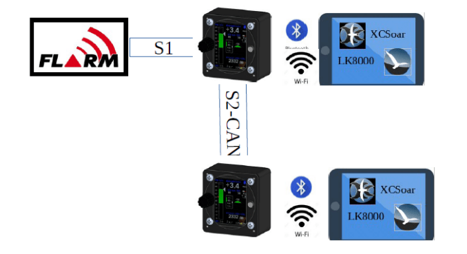
For two-seaters and two wireless navigation systems, the following configuration is available, in which the main device is connected to the FLARM at S1 in the front, and the second display for the rear seat is connected via the CAN bus Data from the XCVario itself is transmitted to the second display via the CAN bus. Only the front device has to be hosed. This is the simplest configuration for two-seaters and only requires a 1:1 patch cable between the S2 interfaces of the front and rear units.
Front device minimum setup:
| Wireless Routing | S1-Routing | S2-Routing | CAN Routing | ||||
| Port | Setting | Port | Setting | Port | Setting | Port | Setting |
| XCVario | Enable | XCVario | Disable | XCVario | Disable | XCVario | Enable |
| S1-RS232 | Enable | Wireless | Disable | Wireless | Disable | Wireless | Disable |
| S2-RS232 | Disable | S2-RS232 | Disable | S1-RS232 | Disable | S1-RS232 | Enable |
| CAN-bus | Disable | S1-CAN | Enable | CAN-bus | Disable | S2-RS232 | Disable |
Secondary device:
| Wireless Routing | S1-Routing | S2-Routing | CAN Routing | ||||
| Port | Setting | Port | Setting | Port | Setting | Port | Setting |
| XCVario | Enable | XCVario | Disable | XCVario | Disable | XCVario | Enable |
| S1-RS232 | Disable | Wireless | Disable | Wireless | Disable | Wireless | Enable |
| S2-RS232 | Disable | S2-RS232 | Disable | S1-RS232 | Disable | S1-RS232 | Disable |
| CAN-bus | Enable | S1-CAN | Disable | CAN-bus | Disable | S2-RS232 | Disable |
Two XCVario, two wired Navis and FLARM
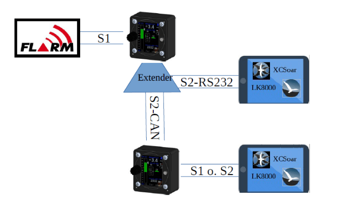
For two-seaters with two wired navigation systems, the picture is similar to the last configuration, the front navigation system can be connected to S2, the rear navigation system to S1 or S2. With a connection via S1 on the second device, the IGC-compatible Flarm port of the standard cable set is ideal if the device also has serial ports according to the IGC standard, or a connection to S2 with a 1:1 patch cable. In this case, the same routing settings “CAN” and “XCVario” as shown for S1 are to be made on the second device instead on S2. When connecting to S2 in the rear cockpit, use one of the extenders as shown in the front unit.
Front device minimum setup:
| Wireless Routing | S1-Routing | S2-Routing | CAN Routing | ||||
| Port | Setting | Port | Setting | Port | Setting | Port | Setting |
| XCVario | Enable | XCVario | Disable | XCVario | Enable | XCVario | Enable |
| S1-RS232 | Enable | Wireless | Enable | Wireless | Disable | Wireless | Disable |
| S2-RS232 | Disable | S2-RS232 | Enable | S1-RS232 | Enable | S1-RS232 | Enable |
| CAN-bus | Disable | S1-CAN | Enable | CAN-bus | Disable | S2-RS232 | Disable |
Secondary device:
| Wireless Routing | S1-Routing | S2-Routing | CAN Routing | ||||
| Port | Setting | Port | Setting | Port | Setting | Port | Setting |
| XCVario | Enable | XCVario | Enable | XCVario | Disable | XCVario | Enable |
| S1-RS232 | Enable | Wireless | Enable | Wireless | Disable | Wireless | Disable |
| S2-RS232 | Disable | S2-RS232 | Disable | S1-RS232 | Disable | S1-RS232 | Enable |
| CAN-bus | Disable | S1-CAN | Enable | CAN-bus | Disable | S2-RS232 | Disable |
Two XCVario wireless, two wireless Navis and FLARM
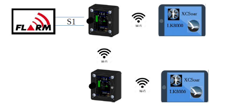
This configuration does not require any cabling between the front and rear devices. Both the navigation system and the two XCVarios can be coupled via WiFi. In Options / Wireless, the front device must be set as the wireless master and the rear device as the wireless client. Since Bluetooth and WLAN are only possible as alternatives, only the WLAN connection is possible, further details on this can be found in the Settings / Wireless chapter. The default for the routing can be used here. Only the setting for S1 on the first device is relevant, as well as the WL routing on both devices.
Front device minimum setup:
| Wireless Routing | S1-Routing | S2-Routing | CAN Routing | ||||
| Port | Setting | Port | Setting | Port | Setting | Port | Setting |
| XCVario | Enable | XCVario | Disable | XCVario | Disable | XCVario | Disable |
| S1-RS232 | Enable | Wireless | Enable | Wireless | Disable | Wireless | Disable |
| S2-RS232 | Disable | S2-RS232 | Disable | S1-RS232 | Disable | S1-RS232 | Disable |
| CAN-bus | Disable | S1-CAN | Disable | CAN-bus | Disable | S2-RS232 | Disable |
Secondary device:
| Wireless Routing | S1-Routing | S2-Routing | CAN Routing | ||||
| Port | Setting | Port | Setting | Port | Setting | Port | Setting |
| XCVario | Enable | XCVario | Disable | XCVario | Disable | XCVario | Disable |
| S1-RS232 | Disable | Wireless | Disable | Wireless | Disable | Wireless | Disable |
| S2-RS232 | Disable | S2-RS232 | Disable | S1-RS232 | Disable | S1-RS232 | Disable |
| CAN-bus | Disable | S1-CAN | Disable | CAN-bus | Disable | S2-RS232 | Disable |
Basic Setup
The following Chapters is dedicated to the setup elements as there are in the device in English language. Because of that those elements are only translated from English in the table of contents here, not in the headlines or select lists in the following chapters about the setup.
MC
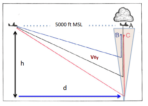
0.5 m/s
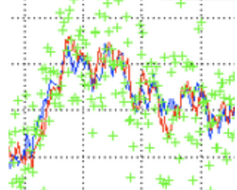
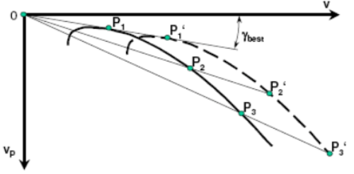
Here the MacCready value (MC) can be set from 0 in 0.1 m/s steps to 9.9 m/s. After confirming with a short press, the Vario is immediately back in normal operation. The MC value can be described as an Optimum Airspeed Selector, according to the mathematics developed by Paul MacCready. This crosscountry “airspeed selector value” is indicates the optimum speed at which a sailplane should be flown between thermals. In the picture on the right, case A shows the optimum setting, B a too low and C a to high MC setting.
Bugs

0 %
Degradation of the flight polar by insects can be adjusted via the parameter Bugs (insects). Here, the coefficients of the polar parabola a0, a1, and a2 are worsened according to the percentage. The flight polar can be deteriorated by this parameter in percentage terms. Whereby the absolute, the linear, as well as the quadratic coefficient are degraded, which equates to a greater degradation at higher speeds. The procedure is identical to the polar degradation procedure used in XCSoar, and is the common procedure for accounting for insects in glider polars.
Maximum degradation is 50% in accordance with XCSoar. Values like 10-20% are realistic for modern profiles. However, older profiles that are more sensitive to rain and mosquitoes, e.g with a LS3, Kestrel or Nimbus 2, can largely exhaust the value range with very heavy soiling.
Ballast

80 liters
39.00 kg/m2
The water ballast can be set in the ballast dialog. In addition, the wing loading resulting from the additional ballast is displayed. 1 liter of water normally corresponds to 1 kg of ballast.
Example: A glider with a wing area of 10 m2 has a setup weight of 260 kg, the pilot weighs 80 kg, 100 liters of water (100 kg) are in the tank. The take-off weight is 440kg, corresponding to the wing loading 440kg/10m2 = 44 kg/m2.
Crew Weight
80 kg
With the “Crew Weight” or pilot and passenger weight, the weight of the pilot, if necessary also of the passenger in twoseaters including parachute and luggage should be recorded. The default setting is 80 kg. A correct weight contributes to the correct determination of the wing loading and thus to a better agreement of the polars with practice, and provides more accurate values for the speed to fly and the net vario, as well as the other weights.
QNH

1013.25 hPa
Dialog for setting the QNH value. On the ground, set the value so that the altimeter display also shows the airfield elevation, or to the QNH value of the nearest ATC.
Airfield Elevation

-1 m
If the value for the airfield elevation is recorded here, the QNH is automatically adjusted to the given airfield elevation after switching on. In the QNH dialogue, the QNH then only has to be confirmed. If you land on another airfield with a different altitude, use the local QNH when switching on, or adjust the airfield elevation to the new altitude if you want to use the auto setup for the QNH. The default setting here is -1 meter, so the feature is switched off and the last recorded QNH is used and must be adjusted conventionally.
Vario and Speed 2 Fly
The settings for the vario display and the speed to fly can be adjusted in the Vario dialog.
Range

5 m/s
The scale of the variometer is set with the range. A range from 1 m/s to 30 m/s can be selected for the min/max values. Default is 5 m/s.
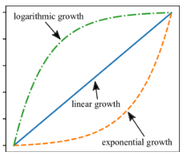
Log-Scale
[DISABLE]
[ENABLE]
With the help of this option, the pointer display of the variometer can be shown with a logarithmic scale. The area around the zero point is stretched, and the areas towards the end of the scale are gathered. The mode has the advantage of being able to display a significantly larger measuring range without losing accuracy around the zero point. Another decisive advantage: This means that relative changes can be better evaluated, which means an improvement in climb of 20% at 1 m/s, i.e. an increase of 0.2 m/s, corresponds to the same way on the scale as relative improvement by 20% at 5 m/s, equivalent to 1 m/s.
Mode
[Brutto]
[Netto]
[Cruise Netto]
With this setting you can choose whether the variometer works as a gross vario, i.e. without taking account of the polar sink rate, or as a netto vario with the polar sink rate being calculated out.
The “Cruise-Netto” setting selects the net setting exactly when the vario is in speed-to-fly mode, otherwise the vario works as a gross variometer, which makes sense when circling, because for the MacCready setting the gross rate is relevant.
Of course, the audio signal also follows the set mode. In the gross setting, the acoustics only report climbing when the surrounding air mass rises faster than the polar sink rate, i.e. the aircraft is actually climbing. In the netto setting, the audio signal is coupled to the net climb, so as soon as the surrounding air mass rises, the acoustics also indicate climb. This makes sense, for example, to better recognize small changes in the surrounding air mass when flying fast ahead, since the sometimes higher sink rate in net mode is otherwise compensated.
Netto Mode
[Normal]
[Relative]
With this setting, the net mode can be further refined. In the [Normal] setting, only the polar descent is taken into account for the current speed, so the variometer display corresponds exactly to the rise or fall of the surrounding air mass. In the display, this setting for the normal net is signaled with “net” in the top status line.
For example, if you circled the net display at 2 m/s, you would have a slightly less effective (gross) climb than the pure net value due to the inherent sink rate when turning, e.g. an LS-4 with an inherent sink rate of 0.6 m/s when turning only 1.4 m/s.
In order to take this into account, the net mode setting [Relative], often also called “Super Netto” (default), also takes into account the inherent sink rate when circling, specifically the inherent sink rate that occurs when circling with a 45° bank angle at the optimal speed would be. So it shows the value that you would have in terms of gross rises if you circled at the point. The display of the vario would be 1.4 m/s in this case, and further reduces the workload in the cockpit, since one no longer has to calculate the value of the expected climb in order to assess whether circling is worth as displayed directly in Super-Netto mode. This setting is signaled with “s-net” in the status line.
Polar Sink
[DISABLE]
[ENABLE]
By selecting [ENABLE] (default setting), the polar sink rate is displayed in relation to the speed in the gross mode of the variometer. With [DISABLE] the display can be switched off, the polar sink rate is then no longer displayed. The polar sink rate is shown in the airliner style as a blue bar, in the retro style as a blue arc starting from the zero point and pointing downwards.
Needle Color
[White]
[Orange]
[Red]
Option for the color of the vario pointer. In the default setting, the vario pointer is white [Orange], but can also be displayed in orange or red (Red).
Center Aid

[Disable]
[Enable]
With the option for the center aid, you can choose to show a center aid in the retro display. The default is [Disable], with [Enable] the centering aid is displayed. The feature is still new and has yet to be tested in flight. In the lower half of the scale, it shows green dots on a circular arc, which increase with the strength of the updraft relative to the flight direction (heading), and is intended to support the pilot in shifting the circle accordingly for better climbing. If there is no magnetic sensor, the course over ground from a possibly connected Flarm or GPS is used as a reference.
Vario Damping
3 sec
Damping controls the time constant for smoothing the variometer display. Normal thermals are inherently turbulent, which means that an undamped vario display provides the pilot with little information that can be evaluated. Time constants of a few seconds are common. Too much damping delays the display with simple low-pass filters. The optimized Kalman filtering, which takes physical conditions into account and thinks ahead, reacts quickly without appearing nervous. The default is 3 seconds. Values up to 6 seconds can be useful for an even smoother display.
Averager
20 sec
This damping controls the time constant for smoothing the digital average variometer display, top center of the display. The default is 20 seconds, so the digital display shows the average climb over the last 20 seconds. This is a fairly common value in many variometer systems, and gives the pilot an indication of the current strength of the thermal. Insufficient attenuation leads to poor legibility and offers hardly any useful information due to the nervousness of the display. The value can theoretically be increased to 60 seconds.
Mean Climb
Minimum climb

0.5 m/s
The Mean Climb min(imum) setting. For the calculation of the average climb, small climb values, which are present, for example, in straight flight at high speed, can be hidden. A modern recommendation (http://aboutgliding.com/005-a-small-error-in-maccready-theory/) In the following, only the core climb when circling should be used for the MC value, and not the climb values in straight flight or when centering. This value defines the minimum climb from which a climb value is still taken into account in the calculation of the mean climb. The default is 0.5 m/s.
Duration
45 min
According to the recommendations, the climb values of the last 3 thermals should also be taken into account as the average climb for the MC value. From the analysis of many flights you can see that a new updraft area is approached about every 15 minutes. This is taken into account with a default setting of 45 minutes for the “Mean Climb dur(ation)”, i.e. only values from the last 45 minutes are taken into account. The value can be changed in minute increments.
Cycle
60 sec
This setting determines how often the mean climb is calculated. The “Mean Climb cycl(e)” defines the period in which this occurs. The default is 60 seconds, the value can be tuned between 60 and 300 seconds. A circle with a 45% bank angle usually lasts about 20 seconds with a glider, 60 seconds corresponds to about 3 circles. This is a good value to gather enough data for the new Mean Climb indicator and to be able to clearly show the trend (shape/color of the diamond) accordingly. Shorter times lead to small values and tend to weaken the trend signaling.
Major Change
0.50 m/s
“Major Change” is the value for the change in average climb, which is graphically represented by a symbol change. If the value is exceeded, the shape of the route changes and the diamond lengthens up or down. The default is 0.5 m/s.
S2F Settings
Damping
5.00 sec
The S2F (Speed to Fly) can also be dampened within certain limits, the default is 5 seconds. Greater dampening smoothes but also delays the S2F display, so that after leaving the thermal, the speed to fly does not immediately increase in line with the sink. The value can be set in 0.1 second steps up to a maximum of 10 seconds. In modern aircraft with high wing loading and high cruise speeds of over 150 km/h, it makes little sense to react to short thermals. This would even be counterproductive, since unfavorably high load factors then occur due to inertia, which reduces the performance, which speaks for a damping of the S2F. When lined up, it makes sense to react with constant climbing or in a blue hole with constant falling, which is also very possible with a certain amount of damping. The default value of 5 seconds can be tuned by the user.
Blockspeed
[DISABLE]
[ENABLE]
By setting the block speed [Enable], the rising or falling of the surrounding air mass (according to the value of the net vario) is suppressed. Only the load and the MacCready value are then included in the calculation of the optimal speed. The speed that the speed command then displays remains constant in the thermal, which follows the theory that pulling up with typical thermals lasting a few seconds does not necessarily make sense due to the inertia of the aircraft. This was proven years ago by numerical simulation at the Technical University of Munich, and it was shown that the MacCready speed for the upwind case only makes sense from a certain thermal duration of approx. 20-30 seconds (half the period of the phygoid or natural frequency, also called pump frequency) , or if you really want to crank. Some well-known pilots fly this style and achieve good average speeds with it.
S2F Mode
[Vario fix]
[Cruise fix]
[Switch]
[AutoSpeed]
[External]
[Flap]
[AHRS-Gyro]
The S2F ‘Mode’ specifies the procedure used to switch between circling and speed to fly. There are four options. The mode can either be fixed to Vario [Vario] or Speed to Set [Cruise]. The instrument then does not change modes, and remains fixed in either circling or speed command mode. In practice, when flying cross-country, these two settings make little sense, at most the vario mode can make sense if you don’t want to fly according to the speed to fly and always want to see a conventional vario display.
The speed command is always visible, so a speed command is also displayed in “Vario” mode, but this is the optimum circling speed with the current load for the minimum sink in a turn of approx. 45°. The resulting 1.4-fold load factor (+40%) is taken into account with a speed increase of ~20%.
There is also the option of using an external switch, e.g. a stick switch or tactile switch (more modern) on the I panel, better on the stick to change between vario and speed to fly. The switch must of course be operated, which increases the workload in the cockpit, but offers maximum flexibility. If you want to avoid this and if you want the switchover to take place automatically from a certain speed, select [AutoSpeed] (default setting). The speed to switch over can be set in the following menu item: “S2F AutoSpeed”.
In [External] mode, the speed to fly setting is taken over by a second variometer, either coupled via Bluetooth or via the CAN bus from series 2022. The second device can be either the rear or the front variometer, depending on where you put the switches or want to wire the button. Select Switch (or Autospeed) on the device that should react to the switches. On the second device that you want to synchronize, the “External” mode.
Warning: The “Cruise from Master” mode has been replaced by this setting, so synchronization can now also be done from the client.
The [Flap] mode allows you to switch the speed command mode to circling mode via the optional flap sensor. The changeover takes place exactly when the flap exceeds the value of “S2F Flap Pos”.
The [AHRS-Gyro] mode can be used on all devices except the 2020 series, and it automatically switches to circling flight mode if the rotation speed in degrees per second is greater than the “S2F AHRS Deg”. The measured rotational speed is the value averaged over 20 seconds and provided with a hysteresis of 20%, it is only switched back when the value is 20% lower than the set value.
S2F Switch

[Switch]
[Push Button]
[Switch Inverted]
[Disable]
The type of speed command switch can be set, a switch [switch] is preset, but a button [push button] can also be selected, which changes the setting each time the button is pressed. This can make sense, for example, when using a Stefly stick input device equipped with buttons. The [Switch Inverted] option stands for a switch with the reverse function, i.e. the speed command mode is then selected when the switch is open instead of when the switch is closed. The switch can change mode at any time, even if set to [AutoSpeed], [Flap], or [AHRS-Gyro], unless set to [Disable].
S2F AutoSpeed
100 km/h
This is the speed in AutoSpeed mode at which the variometer changes from circling to speed command or cruise mode. The default is 100 km/h. With higher wing loading and modern gliders, the value can be set correspondingly higher.
S2F Flap Pos
1
This setting defines the flap position at which the S2F mode should be switched in the “S2F mode” [Flap]. By default, the flap position is set to +1.
S2F AHRS Deg
12 °
This sets the threshold for the rate of rotation in degrees per second at which the device switches to S2F mode in [AHRS-Gyro] mode. Small values switch to thermal mode early on when circling, while larger values switch with a delay due to averaging over approx. 20 seconds. A typical circle with a duration of 30 seconds has a rotation rate of 360/30 = 12° degrees per second, which is the default.
Hysteresis
5 Seconds
With the hysteresis, the automatic, controlled by the airspeed switching (AutoSpeed mode) to target flight can be calmed down. Without hysteresis, the mode may switch back and forth frequently at an airspeed around the set AutoSpeed. A hysteresis of 5 Seconds (default setting) switches to speed to fly mode when the speed is bejond the threshold for the given hysteresis time.
Arrow Color
[White/White]
[Blue/Blue]
[Green/Red]
The color of the speed to fly arrow can be set individually under “Arrow Color”. The first color is for the up arrow, the second color is for the down arrow. The last arrow is displayed in a different color if the range is exceeded. 3 arrows are displayed with the levels 10, 20 and 30 km/h. If the deviation is more than 30 km/h, the case of exceeding is given.
Electronic Compensation
With electronic compensation, you can optionally achieve total energy compensation for the Vario without a TE nozzle. The feature is still in the optimization phase, but already works in principle.
Good electronic compensation requires well-placed and functional static and dynamic pressure taps. Many factors play a role here, starting with the mass of the air trapped in the pressure lines, pressure changes along the fuselage and in the wing area, accelerations and more. It is therefore advised to generally use TE nozzle compensation, which works better in most cases. The parameters that play a role in good compensation can be found in the .pdf scan of the following paper, which Mr. Brözel from ILEC compiled at that time: https://xcvario.de/wp-content/uploads/2021/11/GliderInducedErrorsinTotalEnergyVariometry.pdf
eCompesation
[TEK Probe]
[EPOT]
[PRESSURE]
The default here is [TEK Probe] means no electronic compensation and today is the recommended way once your glider has a TEK probe. The settings [EPOT] or [PRESSURE] enables the electronic compensation. In this modes the TEK nozzle pressure is no longer relevant and in principle does not need to be connected. If those setting is selected, only the pressure connected to ST, the static pressure, is used. This can make sense if no TE nozzle is available. Two different methods are available by today.
The first method [EPOT] calculates from true airspeed the potential energy expressed in meters and joins this with the barometric altimeter to create the vario signal. This method is more accurate in terms of mathematics, hence is more sensitive to dynamic effects what can be an issue in high performance gliders.
The second method [PRESSURE] is new and experimental is based in pressure readings from ST and PI port, and directly joins this pressures in the same way as the TEK probe does. The second method might bring better results in dynamic situations, so maybe more useful for high performance machines, flight tests shall bring a clearer picture here, you may try it yourself and give us feedback.
Adjustment
0.00 %
Both methods for electronic compensation can be tuned by this parameter. The compensation can be adjusted positively or negatively in 0.1% steps up to +/-50% using this percentage factor. This factor decreases or increases the theoretical kinetic energy, which is converted into height during hoisting (V2/2g). In the case of under-compensation (vario shows increase when pulled up), the value should be increased until the display is correct. The same applies to overcompensation with negative values. It is also advisable to increase the preset damping of the Vario from 3 seconds to at least 5-6 seconds in order to minimize transient effects (short-term deviations). The rapidly converging Kalman filter then still reacts sufficiently quickly to changes.
Similar effect for adjustment is there when the pressure method is used, then this factor applies to the total (PI) pressure that is being subtracted from the static pressure.
Audio
Audio

The sound generator is an important part of an electronic variometer to improve safety in the cockpit, as it allows you to look out in order to pay attention to other aircraft. The tone changes in pitch and interval between the pauses (or a second tone) with the vario or speed command indicator, and is emitted through the internal speaker on the rear of the housing or a plugged in external speaker.
Volume Options
Current Volume

4%
Display of the current volume setting as set by rotary.
Current->Default
[Cancel]
[Set]

This setting takes over the current volume as is set by rotary at that time for the default volume on next start.
Default Volume
10 %

In this setting, the volume that is used after switching on the device is configured. The default is 10% volume.
Max Volume
100 %

In this setting, the maximum possible volume of the device is configured. The default is 100% volume. If the loudspeaker used, e.g. with an external loudspeaker, shows distortion at the maximum volume, or if a limit is desirable, the value can be reduced here. For example, a setting of 50% reduces the volume by about 6 dB.
Equalizer
[Disable]
[Speaker 8 Ohms]
[Speaker 4 Ohms]
[Speaker External]
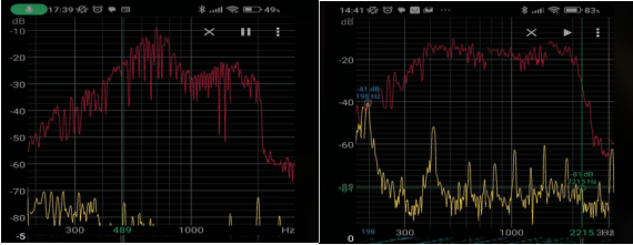
The audio equalizer ensures a uniform frequency response of the audio output, see image on the right (red curve). In the picture on the left you can see the frequency response of the speaker without the equalizer switched on according to [Disable]. The equalizer increases or decreases volume as a function of frequency, as shown here, to attenuate the speaker’s resonant frequencies at 800 and 1600 Hz, as well as boost other areas to achieve an overall balanced frequency response over a wide frequency range (right image). The most commonly installed 8 ohm speaker is selected by default, some devices were delivered with a 4 ohm speaker, which differs slightly in the frequency response. If the setting of 8 ohms does not fit, or if an external loudspeaker is used, then switch to [Speaker 4 Ohms] or [Speaker External]. The correct setting has been found when approximately the same volume can be heard for all frequencies. The series 2023 varios have a speaker with a flat frequency response and do not need equalizer so the default in recent SW builds is [Disable].
Frequency Response

30 %
Since the sensitivity of human hearing increases continuously by approx. 6 decibels per octave in the range from ~30 Hz to 4000 Hz, higher tones sound significantly louder than lower ones, or low frequencies can hardly be heard at a comfortable volume from high tones . This setting takes this into account and reduces the volume per octave by the specified factor. A factor of 50% (amplitude) would correspond to an attenuation of exactly these 6 decibels, since the dynamics of the system are limited, 30% is preset, which represents a very good compromise. If higher frequencies are perceived less well, which is usually normal in the second half of a pilot’s life, this value can be reduced to 0%.
STF Volume
[Disable]
[Enable]
With this feature, which adjusts the volume separately in Vario mode and in speed-to-fly mode, the volume can be adjusted to the different acoustics in the cockpit when circling and in fast flight. In older gliders flying at high speed, a higher volume is often necessary so that the sound can still be heard. The feature takes some getting used to and is switched off by default. With [Enable] it is activated.
Mute Audio

Options to mute audio in different situation like in sink, in setup, generally and disable amplifier in order to save a bit power.
In Sink
[Stay On]
[Mute]
Decide if audio shall be mute or not when you are in a sink.
In Setup

[Stay On]
[Mute]
Decide if audio shall be mute or not when you enter setup menu.
Generally

[Audio On]
[Alarms On]
[Audio Off]
Decide which features of audio that shall be on, vario and speed to fly audio, or only alarm or no audio.
Amplifier
[Stay On]
[Shutdown]
Decide if the digital audio amplifier shall be just muted or shutdown during silence. Note that the amplifier needs ~200 mS for starting up, so there is a small delay when shutdown mode is selected.
Turning off the amplifier saves power (approx. 3-4 mA at 12V), and suppresses residual noise from the system, the vario does not make any noise.
Cruise Audio
[Speed2Fly]
[Vario]

This setting is used to select which sound signal is generated in speed command mode. In the [Speed2Fly] speed command mode, a tone is generated which signals the deviation from the speed command. If the airspeed is too high, a progressively higher, optionally interrupted tone is generated, if the airspeed is too low, a lower tone. In the [Vario] setting, the audio signal remains in the vario setting and can, for example, signal net climbing if the vario is set in “Net Mode” or “Cruise Net Mode”. For more information, see the “Vario Mode” setup.
Tone Styles
CenterFreq

500 Hz
Specifies the center frequency of the tone generator (sine) and can be modified in 10 Hz steps between 200 Hz and 2000 Hz. The default is 500 Hz.
Octaves

2.00 fold
This determines how many octaves the tone change extends between the lowest and the center frequency (Center Frequency) and the highest or lowest tone. The value can be changed in 0.1 steps between 1.5 times and 4.1 times. The default is 2x, which means that with a center frequency of 500Hz, the highest tone is 1000Hz and the lowest tone is 250Hz. Too high a value produces tones outside the optimal spectrum for the loudspeaker and human hearing.
Dual Tone

[Disable]
[Enable]
This setting is used to select whether a simple tone [single tone] with short interruptions is desired (di di di di) or whether the vario works in two-tone mode [dual tone] (di da di da). The default mode is with single tone and interruptions.
Dual Tone Pitch

12%.
This setting is only relevant in two-tone mode. It indicates the pitch, i.e. the pitch change of the second tone. The second tone is shifted up in pitch by this percentage. The default is 12%.
Chopping
[Disabled]
[Vario Only]
[S2F Only]
[Vario and S2F]
With audio in vario or speed to fly (S2F) mode, the sound can be selected at values above zero with short interruptions (100 mS), the frequency of which increases with the displayed vario or S2F value. This interruption (chopping) can be switched off [Disabled], or apply only to Vario [Vario only] or the speed command [S2F only]. A fourth option is a break for both modes [Vario and S2F], which is the default. The maximum interruption frequency when the scale is struck is exactly 10 Hz, the minimum frequency is 1 Hz. In between, the frequency increases linearly with the display value.
Chopping Style
[Soft]
[Hard]
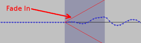
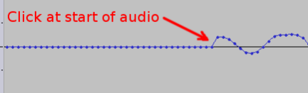
If the sound is interrupted by chopping, a certain “click” sound is heard when switching on and off, this is due to the spontaneous square-wave power change which generates harmonics. In order to minimize this effect, the [Soft] setting slowly ramps up the power within a few milliseconds (fade-in) and slowly ramps it down again when switching off (fade-out). The setting is a matter of taste, the default is the soft mode, which is mostly perceived as more pleasant.
Variable Tone
[Disable]
[Enable]
Between chops enable or disable frequency changes. The sound may appear a bit ghostly when this feature is enable, but the feedback is more direct than in disabled mode.
Range
[Fixed 5 m/s]
[Fixed 10 m/s]
[Variable (=N m/s)]

This determines whether the tone generator follows a fixed range setting [Fix 5 m/s] or [Fix 10 m/s] or follows the current variometer range setting [Variable (=N m/s)]. The range determines from which value the tone generator outputs the highest or lowest frequency and interval sequence. It can make sense to assign the range dynamically in the case of a weak climb. With a dynamic setting and a range of 2 m/s of the vario, 2 m/s then sound the same as 5 m/s with a fixed setting. The default is [Fixed m/s].
Deadbands
[Lower Vario] :  – 0.30 m/s

[Upper Vario]: 0.30 m/s

[Lower S2F]: – 10km/h

[Upper S2F]: + 10km/h
The deadband is the area where the vario does not emit any sound (muted). There is the [Lower ..] setting for the negative value and the [Upper ..] setting for positive values. The default is +-0.3 m/s for the vario deadband. The deadband helps to hide small climb values and to ensure silence on the ground without having to turn down the volume. The target travel (S2F) also has a deadband, preset are -+10km/h only when the target travel difference from this value is exceeded is the muting canceled.
Audio Exponent
1.00
With this option, the relationship between the pitch and the Vario (or S2F) value can be optimally adapted to the circumstances. The default is 1.0, i.e. a linear relationship. Values less than 1, e.g. 0.5 produce a magnifying glass effect around the zero point. This is either a setting for flat land, when mainly small climb values are to be expected. Small vario values then lead to larger changes in the sound, the pilot is already alert with smaller climb values. Values greater than 1, e.g. 1.5 dampen the audio signal for small climb values. This, on the other hand, draws attention to high climb rates. This can make sense in the mountains if very good climb rates are to be expected.
Glider Details
In the loading/polar dialog, the right polar for the aircraft type is selected, masses can be adjusted and the polar that is set can be tuned manually.
Glider Type
[User Polar]
[Antares 20E]
[ASK 21]
:
With this the polar for the corresponding type of aircraft can be set.
There is also a polar [User-Polar], e.g. for an aircraft type that is not contained in the library. the
[User Polar] is selected by default and corresponds to the values for an LS4a. There is an extensive and constantly growing library.
The current list of supported polars in the library can be found here: https://github.com/iltis42/XCVario/blob/master/main/Polars.cpp
Note: When updating from older software versions before mid 2021, the set polar must be checked after the update, the adoption of the setting may not be correct. With an upgrade from newer software versions from June 6, 2021, the problem is solved and the check is no longer necessary.
Polar Points
[Wingload]
34.4 kg/m2

[Speed 1]
80 km/h

[Sink 1]
– 0.66 m/s

[Speed 2]
125 km/h

[Sink 2]
– 0.97 m/s

[Speed 3]
175 km/h

[Sink 3]
– 2.24 m/s
Under PolarAdjust, the reference wing loading and the sink values for the individual speeds can be modified. The reference wing loading is the value at which the polar was flown and is usually given with the polar. If the current wing loading is higher even without ballast, then this must be set under “Fixed Ballast” see below. Normally, the reference wing loading should not be changed and must agree with the information from the polar. For this wing loading, the corresponding sink values [Sink 1,2,3] are to be set at three points according to the polars from the flight manual at the corresponding speeds [Speed 1,2,3]. The respective decrease is recorded as a negative value. Ideally, you should take the first speed around the lowest sink rate, then an average speed and a reasonable highest speed which is relevant for the cruise mode.
Modifications to the selected polars are reset by selecting a different aircraft type. Normally, only the aircraft type has to be set, an adjustment of the above parameters is not normally necessary, further aircraft types are promptly integrated into the library by XCVario on request, and are immediately available after a SW update.
Max Ballast
160.00 liters
The maximum possible water ballast can be modified here. This parameter is usually given by the aircraft type and comes from the polar library according to the manufacturer’s information, but can vary due to modifications such as adding winglets or installing other water bags, and can be modified here accordingly.
Wing Area
10.5 m²
Here the wing area can be modified. These parameters are actually given by the aircraft type, but can vary due to modifications such as attachable wings or winglets, and can be modified here accordingly.
Empty Weight
265 kg
With “Empty Weight” or empty mass, the empty weight or empty mass can be set more precisely. Gliders tend to get heavier over time, not only because of the installation of instruments, the addition of winglets or repainting, but also the CFK or GFK itself draws water over time and becomes heavier as a result. In order to take this into account, the empty weight can be set to a higher value than that which was used as the basis for determining the gliding polars in the comparison flight. As a default, when selecting the polar, the empty mass is entered from the flight weight minus the pilot’s weight. A higher empty mass thus improves gliding at higher speeds and, like normal water ballast, contributes to increasing the wing loading.
Options
Student Mode

[Disable]
[Enable]
With the “Student Mode”, if “Enabled”, only the settings necessary for the flight are shown in the setup menu, such as MacCready, Audio Volume, QNH Setup, Ballast, Bugs and Airfield Elevation. All other setting options are then hidden. The mode can be ended again by turning in the “Expert Password” 271 on the rotary switch and restarting. Then all setup options are displayed again.
The mode can make sense for clubs to prevent unintentional twisting of an important parameter in a training aircraft. By default, this mode is turned off.
Airspeed Mode
[IAS]
[TAS]
[CAS]
[Slip Angle]
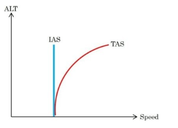
In addition to IAS (Indicated AirSpeed), i.e. the displayed speed, which deviates slightly from the true value in terms of height, the TAS (True AirSpeed) and CAS (Calibrated Airspeed) is also available as an alternative.
The TAS increases at higher altitudes and corresponds to the true speed and is comparable with the ground speed of the GPS without wind, which shows a higher value at higher altitudes. The “Slip Angle” setting shows instead of the speed an estimate of the slip angle in degrees determined from the acceleration values, roughly corresponding to the thread, which plays a role in the wind calculation in straight flight.
Auto Transition

[Disable]
[Enable]
With this setting, the altimeter can be automatically switched to QNH standard 1013.25 hPa from the “Transition Altitude”.
Transition Altitude
50.00 FL
With this setting, the country-specific “Transition Altitude” can be set as Flight Level (FL). This is only relevant if the automatic transition from the previous point is switched on (Enable). Below the transition altitude, the QNH setting applies to the altimeter, above that it switches to QNE according to the standard 1013.25 hPa.
Units
Units
For international use, the units for the variometer, the airspeed the altimeter, temperature, QNH and distance can be set as desired. The setting options are as below, the defaults are printed in bold.
Altimeter
[Meter (m)]
[Feet (ft)]
[Flightlevel (FL)]
Airspeed
[Kilometers/hour (km/h)]
[Miles/hour (mph)]
[Knots (kt)]
Vario
[Meter/sec (m/s)]
[Feet/min x 100 (fpm)]
[Knots (kt)]
Temperature
[Celcius]
[Fahrenheit]
[Kelvin]
QNH
[Hektopascal]
[InchMercury]
Distance
[Meter (m)]
[Feet (ft)]
Flap (WK) Indicator
Flap (WK) Indicator

The “Flap Indicator” shows the pilot the optimal setting of the flap depending on the wing loading and the speed in straight flight. The default setting for the flap indicator is switched off and can be switched on with [Enable]. The speeds from the flight manual for the wing loading of the polars entered should be recorded.
Flap Indicator
[Disable]
[Enable]
Here you can [Enable] or [Disable] the feature of the flap display. By default, the display is off. The optimal latching of the flap is indicated with the green triangle as shown above. The green triangle moves vertically according to the set speed ranges for the flap positions.
Max postitive Flap
2
Two positive flap positions are preset. The number of positive flap positions can be selected here. Between 0 and 3 positive flap positions are available. According to this setting, these flap positions are visualized, as well as menu items for recording the speed ranges, and the values for calibration are recorded if the sensor is present.
Max negative Flap
-2
As above for the number of negative flap positions.
Takeoff Flap
1
Here you can set which flap position should be displayed when there is no dynamic pressure on the ground. Normally this is the position required for take off and is usually found in the flight manual. Depending on the load and the wind situation, the setting may require correction. In case of doubt, the flap position specified in the flight manual for the respective situation always applies.
Flap Speeds Setup
The optimal speed ranges are recorded under the following entries, shown here for three positive and three negative flap positions. Only those values are used which are given by the maximum positive and negative setting.
Speed +3 to +2
70.00 km/h

Speed +2 to +1
78.00 km/h

Speed +1 to 0
88.00 km/h

Speed 0 to -1
105.00 km/h

Speed -1 to -2
165 km/h

Speed -2 to -3
195 km/h
Flap Position Labels
Flap Label +3:
L

Flap Label +2:
+2

Flap Label +1:
+1

Flap Label 0:
+0

Flap Label -1:
-0

Flap Label -2:
-2

Flap Label -3:
-S
In order to enable the display to be adapted to the labeling of the flaps in the cockpit, a label can be selected here for each flap position, named in the software from -3 to +3.
Each position can be chosen from a range of digits from -9 to +20 and letters such as N,L and S. Additional letters or numbers can be added on request. The labels on the flap lever can represent positions or degrees for the inclination of the flap, this varies from manufacturer to manufacturer.
For reasons of space, the plus sign is only displayed for digits less than 10. Negative values are supported up to -9 (so far sufficient for all models considered) and are always output with a minus sign.
Flap Sensor
[Disable]
[Enable IO-2]
[Enable IO-34]
[Enable IO-26]
This option activates the flap sensor, which was on IO-2 or IO-26 in earlier hardware versions and on IO-34 in later series. The settings for IO-2 or IO-26 can only be used together with the Bluetooth connection. With a WiFi connection, the use of the IO-34 is necessary, this will be supported from the second series in 2021. The display is made using the rectangle, which symbolizes the flap lever. The color of the rectangle changes depending on the position of the flap lever. With a good setting, shelf less than half a flap position, is the color green, otherwise white. In the case of a more serious error, more than a complete notch, the symbol also flashes in color red.
Sensor Calibration
[Cancel]
[Start Calibration]
With the help of the flap sensor calibration, the flap sensor is measured for the latched flap positions. With [Start Calibration] the dialog begins, which prompts specified positions to snap. The dialog looks like this:
Set Flap +2
Sensor: 385
Saved
and thus prompts the flap position to be set to +2. The digitized sensor data in the range from 0..4095 are displayed in real time. If the flap is set correctly, the value is saved by pressing the push button and the next flap position is reached. At the end, the completion message “Saved” appears and the calibration is complete. The graphics for the flap display should then be checked. The flap positions must now match the selected flap position.
If this does not fit, e.g. because a position was not locked correctly, the calibration can be repeated at any time. If there are further problems, the installation of the potentiometer should be checked with a multimeter, for example. It is recommended that the potentiometer is installed in such a way, for mechanics see the section on the flap sensor below, that positive flap positions result in smaller resistance or digital measured values and negative positions result in larger values, so that a uniform procedure is used to check, measure and Facilitating support also works the other way around.
The values are proportional to the resistance of the potentiometer. If a separate potentiometer is used, it must be supplied with a voltage of 1.2V on one side; the input has no internal pull-up. In the simplest case, a resistor to the vehicle electrical system is sufficient. A regulated voltage is better.
It is recommended to use the XCVario flap sensor ( https://xcvario.com/product/flap-sensor/ ), which is now available and offered in the XCVario Shop, which works with a regulated reference voltage and an operational amplifier (voltage follower), and is therefore somewhat more precise works as a simple potentiometer, exhausts the full range and resolution of the AD converter, and delivers its voltage independent of vehicle electrical system fluctuations.
FLARM
FLARM
Alarm Level
[Disable]
[Level 1]
[Level 2]
[Level 3]
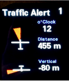
The variometer display is of secondary importance when a collision is imminent. When a FLARM is connected, the device can therefore be used to implement an acoustic and optical FLARM warning, similar to the common LED FLARM secondary display with a higher level of detail and additional information. The default is [Level 1], the FLARM warning is switched on at level 1 and informs you from the lowest alarm level “1” of the FLARM in the event of an impending collision in 13 to 18 seconds, level 2 would warn at 9-12 seconds, corresponding to level 3 only from the highest alert level, i.e. the immediate danger of a collision, between 0 and 8 seconds. Please refer to the description of the FLARM used for further details.
The warning is given on its own screen, which graphically in the form of a red triangle informs about the direction from which the danger is coming, both in the top view and in the horizontal view. An example of a Traffic Alert Alert level 1, the lowest alert level, see right. The danger comes from the front slightly to the left, shown here is a relative bearing of -10 degrees, so the red triangle shows the exact angle, analogously to the horizontal view. Furthermore, the type of warning and the alarm level is output by means of text, e.g. with “Traffic Alert 2”. The direction of approach in the clockwise system, e.g. “2 o’clock”, the relative distance and the relative altitude difference in the selected unit system.
Alarm Volume

[100 %]
The audible warning is designed as a constant and rapidly alternating two-tone tone to distinguish it from other tones and increases in frequency, tone sequence and volume according to the alarm level. In the highest alarm level 3, the warning tone is output with the level set here. At alarm level 2, the noise is reduced by around 6 decibels, at alarm level 1 by around 12 decibels. The default is 100%, the volume can be varied between 20% and 125%.
Alarm Timeout
5 sec
Configure here the time FLARM alarm warning keeps displayed after the Flarm alarm went off. Default is 5 seconds, together with the time the alarm is present this is normally enough time to read the and interpret the display. For feature testing and other purposes a longer time might be appropriate, and in competition even a shorter time may make sense, e.g. when circling in a lift with many other gliders.
FLARM Simulation
[Disable]
[Start Sim]
The simulation of an approach by a second aircraft can be simulated under this menu item. The approach begins to the left below and moves to the right, with a further decrease in distance and height difference, past the bow. Different alarm levels of the FLARM are simulated optically and acoustically. The setup must be exited in order to be able to follow the situation on the screen.
Compass/Wind


Compass/Wind
Compass
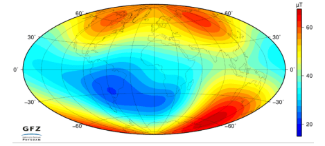
The compass is an optional module for the S2 interface, a magnetic sensor of the latest design, which allows an accuracy of up to one degree deviation with an optimal installation position and calibration. The magnetic sensor measures the earth’s magnetic field in 3D, i.e. in all 3 spatial directions, and has a tilt angle correction (tilt compensation). The sensor gets the inclination data from the AHRS module. For this it is necessary that the sensor calibration of the AHRS sensor is carried out once in its installation position, preferably in flight attitude. It is not necessary to activate the AHRS feature.
The magnetic sensor must be firmly connected to the aircraft in the correct position, the symbolism on the sensor shows an aircraft symbol with tail and wings, this must match the real aircraft and the lettering ‘Top’ must point upwards. There must not be any metal in the vicinity at the installation site, 20 better than 30 cm distance are minimum distances to deliver good results. The compass should not show more than 15°, better only 10° deviation (deviation) in any direction. A good position in a narrow glider fuselage, self-launchers or two seaters with lots of controls, cables and steel parts and various fittings is not easy to find. The cable should not be longer than two meters and should be point-to-point. If a flap sensor is also installed, pins 3 and 4 on interface S2 must only run to the magnetic sensor. Do not use an Y-Piece for an optional flap sensor but the S2-Extender if you got both. Otherwise, reading errors and even failure of the compass are possible.
For reasons of space, the display of the magnetic heading is currently only supported in the retro display or the UL style.
In the following menu items, its settings as well as the calibration of the sensor or the compensation of the deviation can be carried out.
Sensor Option

[Disable]
[Enable I2C]
[Enable I2C no Tilt Comp.]
[Enable CAN Sensor]
With this, the type of magnetic sensor can be selected or the sensor can be switched off. By default, the magnetic sensor is switched off [Disable]. In the [Enable I2C] setting, a simple magnetic sensor connected to S2 with an I2C interface is selected, which compensates for the tilt angle (English Tilt Compensation). In the setting without tilt compensation in the next point, the usual compass rotation error up to an inversion of the display values can be expected. This setting is essentially only for test purposes, e.g. for a test setup on the top of a car. The [Enable CAN Sensor] setting enables the use of a new magnet sensor type with CAN interface as well with tilt compensation, which means that the serial interface on S2 remains free and can be used for other purposes, e.g. for the serial connection to an OpenVario. Furthermore, there is no restriction on the cable length for the CAN interface (max. 2 meters with I2C), the CAN magnetic sensor can therefore be installed at any point.
Note CAN: When selecting the CAN type, the CAN interface must be switched on in the system menu, the setting 1000 Kbit is recommended, other data rates are also possible. The sensor should also be plugged in when the compass is switched on, otherwise the software will query the module regularly, which will generate unnecessary CPU load in the event of an error.
Sensor Calibration
[Cancel]
[Start]
[Show]
[Show Raw Data]
With this option, the measuring range of the magnetic sensor is calibrated in the same way as you know it from the compass module of a mobile phone. The calibration must be carried out again if the strength of the earth’s magnetic field changes, this is the case, for example, if you move to a different region on the globe. Normally, it is sufficient to carry out the calibration once.
For the purpose of calibration, the sensor must be swiveled in all spatial directions, which must be done before the sensor is permanently installed in its installation position at a location that is as free of metal or magnets as possible. The minima and maxima of the magnetic field strength in the individual spatial directions X,Y,Z are recorded and permanently stored in the non-volatile memory of the XCVario. Calibration is complete when the three displayed scale values (X, Y, Z scale) are close together and no longer change. In the sensor dialog, the measured field strength for the individual directions X,Y,Z is displayed live as a percentage of the maximum value of 2 gauss to the right of the scaling value in brackets.
example:
X Scale=95.2 (-5.2)
Y-Scale=100.4 (3.9)
Z-Scale=102.1 (13.9)
The best results are achieved if you calibrate the 3 directions individually and make sure that each direction X,Y,Z displays the maximum possible positive field strength once, e.g. (+18.5), and then and in the opposite direction, i.e. rotated 180 degrees, and with that the maximum negative display shows eg (-18.5). This is to be carried out for all 3 spatial directions in both directions. The corresponding spatial direction will turn green if the maximum values have been reached. This is the case when the other two directions are at zero or close to zero (display value less than 1.0), the other two direction sensors are then orthogonal to the earth’s magnetic field. A small graphic with maxima and minima, as well as the current measured values for the six directions X,Y,Z, positive and negative, makes calibration easier.
The X-axis of the sensor runs across the board (i.e. along the short side), the Y-axis along it (along the long side), and the Z-axis runs exactly perpendicular to the surface of the board.
Attention: The inclination, i.e. the inclination of the field line of the magnetic field to the earth’s surface, is between 62° and 70° in Germany (steeper in the north), the sensor for calibration is therefore at an angle of about 35°, namely inclined to the south, compared to the horizontal hold to capture the maximum value. Once you have found this, you rotate the sensor in exactly this position by 180° around its own axis, where this value is inverted. Then the sensor is rotated 90° in a different direction for the next axis.
The saved results of the calibration can be viewed at any time under the [Show] option.
With “Show Raw Data” the raw measured values, the sensor data, can be delivered in real time. An example is below:
X = 3397
Y = 1874
Z = 5420
Raw magn H= 48.0 uT
Cal magn H= 48.5 uT
Here, the X, Y and Z values are the digital values of the AD converter for all three spatial directions. The value 8192 corresponds to 1 Gauss or 100 µT. And the “Raw Magn H” is the sum of squares of the values, i.e. the amount of the field strength in µT. The normal field strength in Germany is around 49 µT and should show around this value unaffected. The “Cal magn H” is shown when the sensor is fully calibrated, and should not deviate more than 2% from the raw value, if the difference is much more, this can indicate an incorrect calibration.
Note: No meaningful directions can be determined without the sensor calibration, so the display remains switched off until then. A faulty, incomplete calibration can lead to deviations in the magnetic heading.
Setup Declination
0°
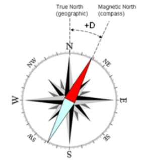
The local spatial variation or declination, source e.g. ICAO map or from airfield data on the Internet, can be taken into account with this parameter. A negative spatial declination, for example -2 degrees, corresponds to a deviation of the magnetic needle to the west. A positive spatial declination of e.g. 2 degrees corresponds to a deviation of the magnetic needle to the east. This setting can make sense if you start at a different location with a different local variation without wanting to carry out a new calibration.
Auto-Deviation
[Disable]
[Enable]
When “Auto-Deviation” is switched on, the deviation is determined automatically, so it does not need to be compensated for manually, as is possible in the following point. This setting is part of the new method for wind calculation TAWC (Tesla Assisted Wind Calculation), which uses the direction information from the earth’s magnetic field, but calculates the compensation for the deviation in a control loop with the help of the wind information from the circling flight. The wind triangle is fed with the basic vector and the wind from the circling flight, and the result is a calculated vector for the heading and the airspeed, with which the deviations in the compass and the airspeed can be perfectly adjusted. The determined values are saved in the non-volatile flash memory approximately every hour. The procedure can only be used if there is at least a crank share of 20%. In pure straight flight, e.g. in a UL, manual deviation compensation at the compensation station is to be used.
Setup Deviations
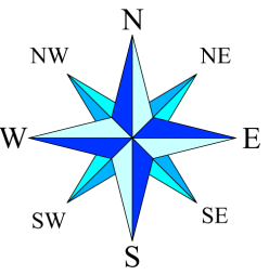
This compensates the deviation of the compass in its installation position in the aircraft. Each direction can be set separately via the dialog. This corresponds to the step-by-step creation of a deviation table; the software uses these values to carry out an approximation for all directions. To compensate for the deviation on the ground, the aircraft must be rotated precisely in eight different directions with the wings level. For this purpose, some airfields have a compensation area with a compass rose attached to the ground, which makes this easy to do. If this is not an option, the direction can be determined with the help of an accurate compass, e.g. on the wing.
For complete compensation, all 8 directions must be selected and the calibration started and ended by pressing a button. After confirmation, the value is stored in non-volatile memory and you can move to the next direction.
Direction: 000
Direction: 045
Direction: 090
Direction: 135
Direction: 180
Direction: 225
Direction: 270
Direction: 315

Two different effects are compensated for in the specific installation position, the so-called “soft iron effect” which is caused by the influence of non-magnetic metals on the earth’s magnetic field, such as nickel or iron, and bends the magnetic field. There are also the “hard iron effects”, metals which are magnetic themselves, i.e. produce their own magnetic fields and normally emanate from magnets such as a loudspeaker.
Show Deviations
The deviation values can be displayed under this point, for all eight directions for which the deviation was saved, whether it was determined manually through compensation as in the previous point, or calculated using the AutoDeviation feature. A small graphic illustrates the course of the deviation curve. Ideally, the curve should be continuous and have a sine period without further oscillations.
Reset Deviations
[Cancel]
[Reset]
An existing deviation table as created in the previous point can be deleted here.
Setup NMEA
Setting the NMEA sentences generated by the compass module.
Magnetic Heading

[Disable]
[Enable]
Turn on the generation of NMEA sentences for the magnetic course, which points in the direction of magnetic north. The corresponding NMEA sentence for this is $HCHDM.
True Heading
[Disable]
[Enable]
To generate the NMEA for True Heading, according to $HCHDT, a spatial variation (declination) must be recorded and the calibration carried out.
Damping
3.00 sec
Damping calms down the compass display, the default is 3 seconds, which is usually sufficient to get a stable display. If the displayed value is not stable in individual cases, e.g. due to electrical lines or other sources of interference, the damping can be increased slightly. The settling times increase accordingly.
I2C Clock
100 KHz
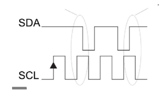
The clock of the I2C bus (SCL) to the magnetic sensor, which is outside the housing, can be set here. 100 KHz is the manufacturer’s recommendation for the chip. If, for example, problems arise with this due to long lines, such as a sensor not being found during calibration or no display being visible, the frequency can also be lowered.
Show Settings
Shows an overview of the most important settings and whether the measuring range has been exceeded (sensor overflow).
Wind Calculation
[Disable]
[Straight]
[Circling]
[Both]
With this option the wind calculation is switched on. The information is shown in the retro display (below the airspeed).
For wind in straight flight (Straight setting), the compass must be installed and functional, and the sensor calibration must be performed. The wind is calculated as vector subtraction of the air vector from the true heading (TH) of the compass and the airspeed, as well as from the GPS signal of a connected FLARM the ground vector from ground speed and the true course (TC), the course over ground. The deviation can be compensated on the ground or automatically determined in flight. The XCVario must also be connected to a Flarm. The wind in level flight is an important piece of information, since with crank percentages of perhaps only 20%, a glider will be in level flight most of the time. A good accuracy of the compass is important here, the high-resolution 3D magnetic sensor, available as an additional module for the XCVario hardware since series 21 that supports this.
Below is a comparison of the wind display of both methods over an entire flight day on February 7th, 2022 (https://www.weglide.org/flight/178203), at the altitude of the flight with the east wind with approx. 20 km/h in the west from 120° and turning east to south by 150° were announced. Both methods meanwhile give values with good agreement:
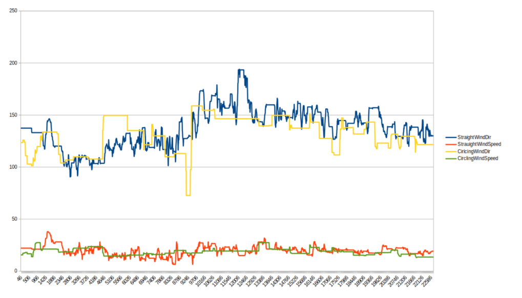
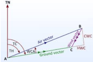
Note: The straight flight setting for the wind calculation has been test in flight and has been optimized with the help of simulations, so it is still under minor development. The releases since summer 2023 look promising. Once the sensor is well calibrated and far enough from metal all is fine.
The wind calculation in circling, is fully stable. The method is identical to the method implemented in XCSoar or Cumulus, from which it originally came.
In the ‘Both’ setting, the wind that has just been calculated is always displayed. Depending on the flight status, circles or straight ahead, the corresponding calculations are carried out here.
Display
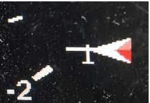
[Disable]
[Wind Digits]
[Wind Arrow]
[Wind Both]
[Compass]
Under the “Display” setting, either the current wind can be displayed digitally [wind digits], e.g. 90°/25 in the format of wind direction/wind force in the retro-style display (below IAS/TAS), or as a small wind arrow within the display [Wind Arrow], or both ways [Wind Both]. By default, the wind indicator is disabled [Disable].
In addition, in the [Compass] setting, the compass course can also be selected and displayed. If there is no wind calculation, e.g. on the ground or during the first calculations, the compass course is always displayed instead of the digital wind. The wind is always displayed in the unit selected for the airspeed.
Arrow Ref
[North]
[Mag Heanding]
[GPS Course]
The “Arrow Ref(erence)” determines whether the wind arrow (Engl. Arrow), relative to the north direction, to the compass course or direction of the longitudinal axis of the aircraft [Mag. Heading] (only possible if a magnetic sensor is present), i.e. to the longitudinal axis of the aircraft, or relative to the GPS course [GPS Course] over the ground. The wind arrow is only displayed in retro-style display mode. For relative plots, a small airplane symbol is drawn at the wind’s tip.
Straight Wind
Filters
Airspeed Lowpass
0.020
The airspeed sensor is continuously calibrated during wind measurement. The low-pass factor determines the speed at which the calibration is adjusted. The default value of 0.020 or 2% means a calibration change of 2% per second. Normally, the default value does not need to be adjusted.
Deviation Lowpass
0.020%
The deviation of the magnetic sensor is also continuously calibrated during wind measurement. The low-pass factor determines the speed at which the calibration is adjusted. The default value of 0.020 or 2% means a calibration change of 2% per second. Normally, the default value does not need to be adjusted.
GPS Lowpass
1.0 sec
This value is used to subsequently filter the course information from the GPS in order to obtain an identical time behavior with the compass. The default value is still being optimized at the moment and may change slightly.
Averager
60
This determines the number of measurements that are relevant for the averaging of the measurements. Measurements are taken every second, a value of 20 (default) means an average over the last 20 seconds. A smaller setting makes the wind calculation more nervous, deviations in the course, e.g. due to side slip, are immediately apparent. At a higher setting, temporary deviations are averaged out.
Limits
Deviation Limit
30 °
The correct deviation of the magnetic sensor is an important parameter and can be calculated automatically with “AutoDeviation” using the circling wind. The tolerance indicates how far the calculated deviation for the current direction may deviate from the last saved value. In the case of values above this, the current wind measurement is rejected as implausible. The default is 30%. Normally, the value does not need to be adjusted.
Sideslip Limit
2.0°
The wind calculation requires a precise heading, which is only guaranteed if the thread remains exactly in the middle. Even with deviations of a few degrees, the accuracy of the wind calculation decreases. Typically, gliders oscillate a few degrees around the vertical axis with each correction due to the roll turning moment, which varies in strength depending on the model. So that the sideslip has little or no influence on the wind calculation, the XCVario continuously calculates the sideslip angle from the sensors and only uses those wind measurements that were obtained at a sideslip angle within a tolerance that can be configured here. The smaller this value, the more precise the wind calculation, but the fewer measurements will fall within the tolerance band. For checking, the slip angle can be shown live in the field of the speed display (IAS/TAS) in the retro display. By default, a maximum sideslip angle of 2 degrees (to the left and to the right) is configured. Values down to 1 degree have already been successfully tested.
Course Limit
7.5°
The course limit specifies the maximum deviation in degrees per second for level flight up to which the wind calculation is carried out. A measurement at higher turning speeds than the configured value is rejected as containing errors. The default is 7.5 degrees per second.
AS Delta Limit
15 km/h
The AS Delta Limit specifies the maximum deviation in km/h for the flight speed in level flight, up to which the wind calculation is carried out. A measurement with a higher variance of the speed than the configured value is rejected as containing errors. The default is 15 km/h change per second.
Straight Wind Status
The status screen shows information on the straight flight wind calculation, such as the input parameters, e.g. the GPS status, deviations in ground speed and airspeed within the measurement window, the underlying compass deviation and more can also be used for diagnosis if the measurement does not work.
Straight Wind enabled : Yes [ No ] (Feature active or not)

Status : Initial [ Calculating ] (status of calculation)

GPS Status: Good [Bad ]

AS C/F: +1.000%/1.000% (Airspeed calibration Info)

Last Wind : 93°/25 (Direction and wind strength in the set unit for speed)

MH/Dev: 68.00/+7.23: (Magnetic Heading and corresponding Deviation)

Wind Age : 120 sec (Age of the last wind measurement)
Circling Wind
When circling the wind calculation, only a few can be adjusted, the procedure is quite simple. The calculation is based purely on the GPS data, a compass module is not necessary for this, therefore also possible on devices of the 2020 series, without a second S2 interface. A Flarm as a GPS data source is the prerequisite for this. During the calculation, the vectors of the ground speed are evaluated and the wind vector is calculated from the directions of the maximum and minimum ground speed. The method also works for circles that are not quite circular; a relatively constant speed when circling is advantageous. The measurement is improved by intelligent filtering (simplified Kalman filter) over several circles, using the quality factor of the measurement from the correlation of the direction of the minima and maxima of the measured speed values. Normally, two to three circles are enough for a precise value, and after just one circle, the wind is initially displayed.
Circling Wind Status
The status screen shows information about the circling wind calculation. This display element can be left again by pressing a button. The information is updated by turning the knob.
Circling Wind enabled : Yes [ No ] (Feature enabled or not)

GPS Status : Good [ Bad ] ( The GPS status)

GPS Satellites: 8 (number of satellites )

Number of Circles: 2.52 (Number of circles that have been rotated since the start of the measurement )

Last Wind : 93°/25 (Current direction/wind strength in the set unit for speed)

Wind Age : 20 sec (age of last wind measurement)

Quality : 95% (Factor for the quality of the measurement (0..100%)

Status: sampling (status of wind calculation)

Flight Mode: circling L (Flight mode, calculations are only made when circling)
Max Angle Delta
90°
The maximum permissible angle difference of the normalized directions for the maximum and minimum speed over ground (ground vector) can be set here. The default is 90 degrees, beyond which a wind calculation no longer makes sense, so a circle with an angle difference of more than 90 degrees is discarded for the wind calculation.
Averager
5
This determines the number of measurements that are relevant for averaging the wind measurements when circling. The measurement is made after each complete circle. A value of 5 (default) means an averaging over the last 5 circles. A smaller setting makes the wind calculation more nervous, a higher setting dampens temporary outliers, e.g. due to speed fluctuations while circling.
Wind Logging

[Disable]
[Enable WIND]
[Enable GYRO/MAG]
[Enable Both]
With this setting, the wind logger can be activated, which is used to develop and optimize the feature, and generates NMEA-like data sets with the $WIND identifier in the normal NMEA data stream of the XCVario. The data record contains a time stamp (second), the basic vector (°, km/h), the airspeed vector, the current wind calculation and the average wind, the last circle wind calculation, the airspeed correction, the flight mode, the GPS status and the deviation.
In order to be able to evaluate the data after the flight, the “NMEA logger” must be set to “On” in addition to this setting to Enable in the XCSoar settings under System→Settings→Logger.
An .nmea file is then stored in the XCSoarData, the logs directory, which contains all the information that the XCVario has sent to XCSoar, including the $WIND data record.
The GYRO/MAG setting outputs additional data fields with the X,Y,Z raw values of the acceleration, the gyrometer and the magnetic sensor.
Beispiel:
$WIND;9747;214.8;115.9;153.1;136.3;58.9;116.6;58.9;116.6;89.8;26.2;5.0,1,1,-16.8
Wireless


Wireless
[Disable]
[Bluetooth]
[Wireless Master]
[Wireless Client]
[Wireless Standalone]
[Bluetooth LE]
The dialog serves to activate and deactivate the interface to a wireless device.
Bluetooth
The default is [Bluetooth], whereby only one device can connect to the XCVario.
Wireless LAN
Another option for supporting multiple devices and multiple drivers in XCSoar is the “Wireless LAN” or WLAN or WiFi setting. Theoretically, up to four devices can be coupled with the Master XCVario, tests were successfully carried out under load conditions with 3 devices. The Vario serves as a WiFi server.
Wireless Client
With this setting, the device can be used as a second display in a two-seater. When switching on, it waits for the Master XCVario, which must be in [Wireless LAN] (=Server) mode. Synchronization via Bluetooth is not possible. If necessary, the waiting screen on the Master XCVario can be ended at the push of a button, and the mode can be implemented again if you have accidentally set this but only have one Vario. In “Wireless Client” mode, the second device receives all sensor data from the Master Vario, such as temperature, airspeed, TE variometer and more.
Also QNH, ballast and bugs are mutually synchronized, while the MacCready value can be set individually, both on the master and on the client device.
Bluetooth LE

The Bluetooth Low Energy or BLE standard is experimental right now. Classic Bluetooth better supports NMEA streaming protocols via RFCOM feature, hence NMEA streaming via BLE notifications using nordic UART service is also possible. There is no support yet in XCSoar or LK8000, hence we expect that this will be part of a future development and so we made BLE already available here. The XCVario will advertise an ID like “XCVario-1234-LE” once BLE is activated.
WL Routing
As an important feature, the routing for all interfaces can now be set up individually without restrictions. The new function enables routing settings, e.g. to declare a task on a navigation device connected to the second device via Bluetooth on the logger or Flarm connected to the front device, or to route the NMEA data on the serial interfaces of the second device to the front device. Settings from a previous software version are automatically adopted and the new switches are preset accordingly. Paths that did not previously exist can now also be set from this software version.
A routing menu in the setup exists for the wireless interface, the two serial interfaces S1 and S2, and for the CAN bus.
XCVario
[Disable]
[Enable]
With this setting to “Enable” you select whether XCVario data is to be output on the wireless interface and commands are to be received and processed via this interface.
S1-RS232
[Disable]
[Enable]
This setting routes the data from the wireless interface to the serial RS232 interface S1. With this setting, the XCVario works as a Bluetooth or WiFi bridge and transparently forwards data from a wireless coupled navigation system with e.g. XCSoar to the serial interface S1. Data from other sources are switched to the interface one after the other using the time multiplex method. The setting is equivalent to the [Wireless] routing setting for the S1 interface. If this setting is enabled, for example if one enables the routing of wireless data to S1-RS232, then routing of S1-RS232 data to wireless is also enabled. The adjustment therefore only needs to be made at one end. This generally applies to all return directions.
S2-RS232
[Enable]
[Disable]
With this setting, the wireless data is routed to the S2 interface and vice versa. In this setting, the XCVario works as before for S1, here as a bridge to the serial interface S2.
CAN-bus
[Enable]
[Disable]
This setting routes the data on the wireless interface to the CAN bus, e.g. if they are also relevant on the second display.
WiFi Power
50%

With the WiFi Power option, the maximum power of the WiFi module is set. The power can vary between 2 dBm and 20 dBm. In the smallest setting of 10%, 2 dBm are emitted, which is usually sufficient for single-seaters where the receiver is mounted close to the variometer, e.g. on the I-board. The default is 50% corresponding to 10 dBm and should be sufficient for all applications, including reception in two-seaters from the rear seat. If the connection is broken in difficult reception situations, e.g. due to closed carbon panels which perfectly dampen radio waves, the performance can also be increased to 100%. This increases the power consumption by approx. 5 mA.
Lock Master
[Unlock]
[Lock]

Under the “Lock Master” entry, a second device can be paired with its WiFi master so that the device only connects to this master XCVario. After selecting [Lock], the ID of the XCVario with the strongest WiFi signal in the vicinity, usually the front device, appears in the dialog and can then be saved with the push of a button. The connection is then only established with this device. When pairing, make sure that no third device is closer than the front device in the cockpit. If necessary, switch it off for the moment of pairing. The pairing can be canceled at any time with [Unlock]. The explicit configuration has the advantage that no other device can be found, e.g. if the front device is not yet switched on when the second device is switched on.
Monitor

[Disable]
[Bluetooth]
[WiFi 8880]
[WiFi 8881]
[WiFi 8882]
[RS232 S1]
[RS232 S2]
[CAN Bus]
The monitor is used to monitor external data connections of the XCVario and can be activated with this dialog. Under [Disable] the monitor is switched off and no interface is selected, while e.g. [RS232 S2] selects the serial interface at S2 and outputs the data transmitted there on the screen. If there is no output, no data is transmitted. After selecting the interface to be monitored, the output of the data on the screen starts with a short push of a button. The screen scrolls, the output can be paused by briefly pressing the button, and the data monitor is ended with a long press. All printable ASCII characters are output here, which applies to all data sets in NMEA format and NMEA like formats (.i.e. GPS data sets). is available as a powerful troubleshooting tool. At the beginning of each data set at the start of a new line, the > character indicates that the data is in the receive direction, and the < character indicates the data in the transmit direction. A line feed occurs after each transmitted record. The output speed has its limits, with fast data connections with high data volumes, individual packets can be lost. However, due to the mostly cyclical transmission, different packets are received, so that the data sought can usually be recorded without any problems. The number of bytes received and sent are shown in the header.
The only known binary protocol is the FLARM protocol for downloading flights, and can only be monitored with it, such as the start of binary mode (FLARM bincom), and the printable characters during transmission.
Example:
Data in sending direction:
<$PXCV,-0.0,0.5,0,1.00,0,24.1
,1003.0,984.5,0.0,0.9,0.8,0.01,0
.00,1.00*30
Data in receiving direction:
>$GPGSV,3,1,12,02,36,257,19,04
,14,080,34,05,23,307,,06,22,206,
*7B
Monitor Mode
ASCII
binary

The “Monitor Mode” is used to select whether the data is displayed in ASCII or in binary format. Normally, NMEA data is sent in ASCII. However, some devices use the binary format, e.g. protocols to set up a radio device, this data can only be displayed in detail in binary format, which represents the binary data as hexadecimal tuple’s (00..ff). The ASCII mode is set by default. Changes here are not saved in the flash, so they have to be set again after the next start.
Custom ID
A separate identifier for the wireless device ID for Bluetooth or WLAN can be set using the “Custom ID”. The prefix “XCVario-” is unchangeable, the number after it can be set as desired via this setup. Six digits are available for this and enables the entry of a complete license plate number, e.g. D-1234 or D-KABC. A competition number or the aircraft type are also conceivable, e.g. ASW24. Together with the prefix, this creates the ID “XCVario-D-KABC”, for example, which can be linked to the smartphone in the usual way. When changing the ID, it is recommended, if the Vario is still paired with the navigation device, to delete the old (now invalid) ID there.
G-Load Display
G-Load Display
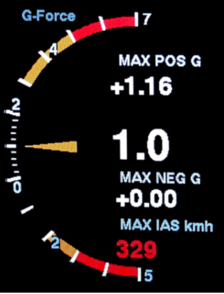
The G-Load Display is an option from the XCVario Series 21 (ff) to display the load factor. If the option is activated, the maximum values are also stored in the non-volatile memory, shown in the G-Load display or can be called up in the setup menu of the G-Meter. It can be set under “System/Hardware Setup/Rotary Setup/Screens” to display the G-meter alternately with the variometer display at the push of a button. In addition, the maximum IAS below the peak value of the negative load factor is also displayed. The peak values are displayed in red as soon as the configured limits have been exceeded.
Activation Mode
[Off]
[Dynamic]
[Always On]
The display of the load factor can either be deactivated [Off] by default, take place dynamically [Dynamic] and occur when the set thresholds for positive or negative load factor are exceeded, or it can be permanently activated [Always On], e.g. for aerobatics.
Positive Threshold
5.0
This defines the threshold for the positive load factor in g (multiple of the gravitational acceleration) at which the “G-Load” display shows. A “1” or 1 g corresponds to normal gravity, the acceleration of gravity. The default is 5 g. The value as well as the following settings can be adjusted in steps of 0.1 g.
Negative Threshold
-3.0
The same setting as in the previous point, only for the negative load factor. The default is -3 g.
Red positive Limit
4.0
The positive limit of the load factor as relevant for the specific aircraft type. The value can be found in the flight manual. The scale shows when this load factor is exceeded as a red area. The default is 4 g. An acoustic warning signal also sounds when the set maximum permissible positive load factor is reached.
Yellow positive Limit
3.0
Second, reduced positive limit for the load factor for the value that applies outside the range of the maneuvering speed, for example. The value can be found in the flight manual. If there is no value there, then the value can be set equal to the previous limit, a yellow area does not then appear. The scale shows when this load factor is exceeded as an orange area. The default is 3 g.
Red negative Limit
-3.0
The same setting of the limit as in the previous point, only for the negative load factor. The default is -3 g. If the limit is exceeded, an acoustic warning signal sounds here too.
Yellow negative Limit
-2.0
The same setting of the limit as in the previous point, only for the negative load factor. The default is -2 g.
Max Positive
Display the lowest measured value of the load factor since the last reset.
Max Negative
Display the highest measured value of the negative load factor since the last reset.
Alarm Volume
100 %
Alarm Volume that is applied during an G-Load alarm.
G-Load reset
[Reset]
[Cancel]
With this the stored maximum values of the previous two points can be reset.
System
Under the system menu you can find the software update, hardware setup like battery, altimeter and airspeed related options, AHRS setup, display setup, and serial interface setup related items that are each documented by their own chapter following in this documentation here.
Software Update

Software Upate
Software Vers.

23.1211-10
Display of the installed software version in calendaric format, example shows version from 11th December 2020 compiled at 10:00 UTC.
Software Update

[Cancel]
[Start]
The software of the device is freely accessible as open source on the github page: https://github.com/iltis42/XCVario.
The Firefox browser is recommended for downloading the file and for the update. With other browsers, problems can occur on some devices due to the “.bin” extension of the file to be loaded due to other links.
Software releases will be published on:
https://github.com/iltis42/XCVario/releases
and can be installed via OTA (Over The Air) method via a WiFi access point of the Vario. To do this, the new firmware, e.g. the file sensor-master-22.0824-2302.bin, must first be saved locally on a WiFi-enabled device, e.g. an Android or IOS mobile phone or tablet, or a laptop or PC with an Internet connection.
Please make sure that the file length of the loaded file corresponds to what the website shows. Typical file lengths are around 1.7 megabytes.
Intermediate releases for testing purposes are accessible here https://github.com/iltis42/XCVario/tree/master/images, but install at your own risk, documentation may not be up to date at the time of publication, and it has been not all tests have been carried out yet, support can only be given to a limited extent.
Then start the software update on the XCVario in the Vario Setup under System/Software Update/ [Start] and switch to the WiFi “ESP32 OTA” on the device on which the file is located. Alternatively, you can jump to the software update mode (shortcut) by pressing the rotary immediately after switching on, immediately after the software version is displayed (first line). Since some newer devices can no longer or do not want to work with unsecured WiFi networks, WiFi was switched to the secure WPA2 PSK standard in February 2022. A password must be entered once.
The password is displayed on the screen and is like the ESP32 XCVario-<nnnn> WiFi access point: xcvario-21 .
Once this is done, the new firmware can be selected (browse) in the browser on the website http://192.168.4.1 and then uploaded. The IP address is now also unified. Specify the prefix http://, in any case if the browser tries to connect with https://, possibly switch off an existing automatic forwarding to http.
The dialog guides you through the download with a progress display and shows the success both on the website and on the variometer. If transmission errors occur, the software is discarded and the variometer restarts with the previous software. There are two download areas, the new software is always written in the non-active area, and to guarantee the functionality of the device at all times.
If the software download was selected on the Vario, but no file was selected and loaded, there is an automatic timeout after 15 minutes and the old software restarts. If you don’t want to wait for the timeout, you can cancel the download at any time by pressing the button on the software’s rotary switch.
If the connection with the WiFi does not work, check whether the device has a check mark that the connection should be maintained even if it is not Internet-capable. If necessary, also answer positively to a corresponding pop-up. As of software February 2022, the XCVario randomly selects a different channel each time the download feature is started, so that a channel can also be found in an environment with many occupied WiFi channels, which enables an error-free download.
After the update, the settings must be checked. Normally, these should be fully adopted from the previous installation. However, new features may be added in new releases and the default settings may need to be changed. Please read the corresponding information in the release notes.
Note: When updating from older versions before mid-2021, it is possible that the polar setting has changed, so check this parameter in any case and correct it if necessary. The problem of the potential shift of the polars is solved from July Release 2, 2021, the check when updating versions after that is no longer necessary.
Factory Reset

[Cancel]
[ResetAll]
Allows a reset to default of all settings of the device. Attention, all settings compared to the default values will be lost. After a reset, make polars and other settings necessary for the aircraft type. A factory reset can also be carried out when downloading the software via the browser using the “Factory Reset” button
Battery Setup

The voltages are preset for a lead-acid battery. For other battery types, adjust according to the manufacturer’s data sheet. In the case of voltages below the “Battery Red” value, the battery display also flashes.
Battery Low
11.50 Volt
Setting the voltage for empty battery when display shows 0% or empty, charge indicator full black
Battery Red
11.75 Volt
Setting the voltage for battery alarm red or display 0-10%, remaining charge flashing red
Battery Yellow
12.00 Volt
Setting der voltage for battery alarm yellow or display 10-20%, charge indicator yellow
Battery Full
12.80 Volt
Setting the voltage for battery full or display 20-100%, charge indicator green
Battery Display
[Percentage]
[Voltage]
[Voltage Big]
The type of display can be modified under this menu item. The battery value can be displayed as a percentage [Percentage] or as a voltage [Voltage] with one decimal place, e.g. 12.5V. [Voltage Big] shows the value in volts without the battery symbol with just a larger, easier-to-read number.
Hardware Setup
DISPLAY Setup

All settings related to the display.
HW Type
[UNIVERSAL]
[RAYSTAR]
[ST7789]
[ILI9341]
The display is pre-configured at the factory with the correct default settings corresponding to the installed display type. Changing the [Type] setting offers no benefits and may even degrade the accuracy of the displayed information. Therefore, adjustments to this setting are unnecessary.
Style
[Airliner]
[Retro]
[UL]
This feature allows you to switch the graphic display mode between “Airliner” style, “Retro” (or Pointer) style, and “UL” style. The previous colored bar display is part of the Airliner style, while the Retro (Pointer) style uses a semicircular display with a pointer, similar to traditional mechanical variometers. Both display modes are explained in greater detail in the corresponding chapters at the beginning of this document.
A new addition is the UL style, which omits the speed-to-fly display and MacCready value specific to gliding. Instead, it displays the QNH value, catering to ultralight pilots.
Color Variant
[W/B]
[B/W]
This option allows you to switch the display color between “W/B” (white on black) and “B/W” (black on white). The default setting is W/B, as it is easier to read in sunlight and gentler on the eyes due to its lower light intensity. The inverted B/W setting is also available and may be preferable if other instruments or the panel use a similar color scheme.
Orientation

[NORMAL]
[TOPDOWN]
By default, the device is configured for installation on the left side of the panel, with operation performed using the left hand on the left edge of the display. For installation on the right side, the display orientation can be inverted using the [Orientation] setting, which moves the rotary knob to the opposite side. The available options are [NORMAL] and [TOPDOWN].
Needle Alignment
[Front]
[Back]
This setting allows you to choose whether the variometer needle is displayed in the foreground ([Front])—overlapping information within its area, such as altitude and wind data—or in the background ([Back]), positioned behind this information.
Display Test
[Cancel]
[Start]
Factory display test for a fully white and black screen in order to detect faulty pixels.
Rotary Setup
Screens
If you prefer to switch only between screens without entering the Setup menu, the Setup function can be assigned to a long press, as described in the previous section. In this configuration, a short press will toggle exclusively between the variometer screen and other screens activated in this menu. Otherwise, with each press of the rotary button, the XCVario cycles through screens such as Variometer > G-Meter > Setup.
G-Meter
[Disable]
Enable
The “Screens” menu allows you to select which screens are accessible by briefly pressing the rotary button. By default, only the variometer screen is displayed, and the button toggles between the variometer and the setup menu. To include the G-Meter screen in the rotation, simply enable this option in the menu.
Horizon
[Disable]
Enable
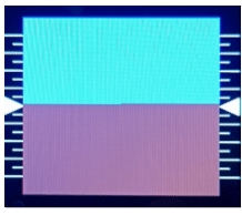
The XCVario, equipped with an IMU and AHRS, offers a simple horizon display for situational awareness, similar to the horizon in XCSoar. The display is square and features a pitch scale. It can be activated via the Screens menu as described previously. Small lines on the scale represent a 5° inclination, larger lines indicate 10°, and the top line corresponds to a 40° inclination.
Important: The horizon is not intended as a blind flight instrument. Instead, it serves as a tool for training and monitoring, such as maintaining the optimal bank angle of 45° or the ideal angle of attack during thermaling. It provides sufficient accuracy for these purposes under normal flight conditions.
Direction

[Clockwise]
[CounterClockwise]
The direction of rotation of the rotary switch (rotary) can be reversed if the rotary switch used has a different coding. This setting is made in the factory and does not normally need to be changed. After a factory reset it may be necessary to make this setting again.
Sensitivity

1 Indent
2 Indent
3 Indent
4 Indent
This allows you to adjust the sensitivity of the rotary switch. There are rotary switches which deliver two pulses per detent (indent). In this case, “2..4 indent per increment” is announced, since otherwise a point would be skipped during a detent. The optimal setting is made in the factory and normally does not need to be changed. It has proven useful to select a setting with “2 Indent” per increment (default setting) so that you do not accidentally move a line or a value when you press the rotary knob.
Rotation

[Volume]
[MC Value]
The presetting for the rotary switch (English Rotary Default) determines which setting is changed in Vario mode by turning the rotary. You can choose between [Volume] for the volume and [MC Value] for the MC value. The default is [Volume]. If the volume control is not required, e.g. when using an external audio device with its own volume control, or if changing the volume via the setup is sufficient, the MC value can also be used here.
The setting [MC Value] makes sense if the audio function is implemented via the external audio input of the radio device, the internal loudspeaker is then switched off. In this case, the volume control of the radio is used, so the rotary can take over the other function.
Setup Menu by

[Short-Press]
[Long-Press]
This setting can be used to select whether the XCVario should activate the setup menu with a brief press of the rotary button (less than half a second) or with a long press of the button. In the “Short-Press” presetting, a short press on the rotary activates the setup menu. If you want to use the feature and switch back and forth between different display screens with a short press, see next heading, it makes sense to first activate the setup menu with a long press. The short press is therefore available to change the display to the next screen.
Gear Warning

[Disable]
[S2 Flap positive]
[S2 RS232 positive]
[S2 Flap negative]
[S2 RS232 negative]
[External]
With the “Gear-Warning” a warning can be triggered in the case of extended brake flaps and retracted landing gear. The magnetic contact on the brake flap must be closed when it is retracted, and the contact on the landing gear when it is fully extended.
Please Note: The warning can be acknowledged by pressing the rotary and then turns off for 500 seconds or about 8 minutes.
Both contacts are switched in parallel with one end connected to ground (GND, battery minus) and the other end connected to pin 6, the flap sensor input, to S2 and connected to +12 volts via a pull-up resistor. Alternatively, pin 4 on S2, the RX pin of the RS232 interface, can be used, and there is an option for external [External] commands that can be send by an external device in order to trigger the gear warning, see the „$g“ commands section for details about this.
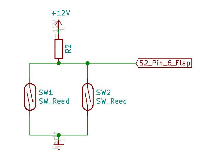
The warning is given optically with the display ! GEAR ! , as well as an audible warning tone, and has priority over the other screens, with the exception of the stall warning.
The feature is available if either the flap sensor or the RS232 interface is not configured, i.e. setting: Disable is mandatory there and is switched off by default, or if you don’t use the flap sensor input.
The switching of the two magnet contacts is shown on the right, both must be designed as normally open contacts, i.e. they must be shot in the vicinity of the magnet. The pull-up resistor R2 is necessary for a high-level and should be in the 100 to 150 Kilo-Ohm range and at least 1/8 watt of power.
With the “negative” options you can also use contacts, which are to be laid in series and then close when the flaps are not locked, or the landing gear is not fully locked.
AHRS Setup

Add devices starting with 2021 series of the XCVario feature an 6 axis AHRS (IMU) sensor chip, which has a sensor for the acceleration in all three axes and a gyro for the rotational speed also in all three axes.
The sensor is used to record the acceleration or the load factor (G-Load), e.g. when circling, which in principle has the same effect as additional ballast, i.e. an increase in the optimal drive, as well as input for the position indicator (artificial horizon) and to deliver the load factor to XCSoar.
AHRS ID
The four-digit “AHRS ID” is required to generate the license key for the AHRS feature. If the feature was not ordered directly with the device, this ID must be specified when ordering the AHRS feature. The AHRS ID is not changeable.
AHRS Option
[Enable]
[Disable]
IIn the default setting and with a set license key (license key), the sensor is Enabled, otherwise Disabled. The option can only be set to Enabled if a valid key is present. With this setting, the processing of the sensor data can be switched off. When switched off, the data fields for the roll angle and the pitch are not forwarded in the NMEA sentences, the corresponding fields remain empty in this case.
AHRS Calibration
The AHRS Calibration catches the inertial sensor orientation with respect to the glider. As a result a small misalignment of the XCVario panel mount does not propagate into its calculation. Specifically the Yaw, that means the gliders longitudinal direction is registered, additionally to zero Pitch and Roll angle.
Axis calibration
[Cancel]
[Start]
[Reset]
According to the manufacturer’s instructions, the sensor must be zeroed once in its installation position for maximum accuracy. There is source of misalignment not only as of minor angle deviations within +-1° from chip tolerances and soldering the chip, moreless also as of installation position of the device in the instrument panel that is usually a bit different from the exact horizontal attitude of fuselage. It is possible to set the sensor to zero with regard to pitch and bank by this procedure on the ground:
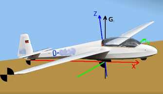
To start the calibration procedure, the glider must to be placed be on a ground that is not inclined, a ground that as flat as possible (check with a spirit level) usually hangars or aprons should be leveled enough for that purpose. Start the procedure by select [Start] and follow the procedure.
You will get prompted to place first the right wing tip down on the ground, and then the left wing. Each step is to be confirmed by pressing to the rotary button. The procedure is completed when both wings are done and the “Finished Success” message appears. The angle the airplane has been shifted will be displayed. After that you may check attitude with the horizon if pitch and bank is correct.
The minimum shift angle is 8° in total that is needed. Smaller angles will result in an Error printed. If this can’t achieved e.g. in an open class glider with large wingspan and low V-Angle, try procedure e.g. without the outer wing or wing extensions. Take care the tip with a foam in that case, if unprotected. If even this is not possible, try to raise the glider in the middle e.g. in assemble position on the fuselage car at your trailor or push it on a ramp with enough height.
Ground angle of attack
12°
Adjust your ground angle of attack, which is included with the above calibration procedure. This can be done independently and after the AHRS calibration. It will align the zero horizon pitch to horizontal flight. Best case is to put the zero pitch to the speed of best L/D usually around 100 km/h in a modern glider (check manual). Raising the ground angle of attack lowers the horizon on the display. The “Ground angle of attack” defaults to 12°.
AHRS License Key

[First Letter]
[Second Letter]
[Third Letter]
[Last Letter]
The four-digit license key for activating the AHRS sensor can be entered via this menu item. 4 letters, numbers or special characters are possible, resulting in several million possible combinations. If the feature is purchased, the license key is set accordingly.
The key is not overwritten during a factory reset.
Note: The AHRS sensor is used to take the load multiple into account for the stall warning and for the polar to precisely calculate the target travel. The variometer has a simple screen for an artificial horizon, and when activated, the data is also forwarded to the flight situation (English situation awareness). Under no circumstances this simplified screen is intended to fly into IMC conditions.
The license key can only be entered on the ground.
AHRS Parameters
Here parameters of the attitude and heading reference system can be tuned. Normally no change is required. Changes can cause changes and inaccuracies in the artificial horizon, so normally do not make any changes here. The optimal default setting is the value printed here in bold.
Gyro Max Trust

100x
This factor determines the maximum trust in the rotation angle sensor (gyro sensor) compared to the acceleration sensor for the position indicator. The 3D vectors of the acceleration sensor, cleaned of the centrifugal force, are merged with the values for the rotation angle of the gyro sensor; the optimal value is as high as possible without the gyro drift causing static position deviations.
Gyro Min Trust
20x
This option changes the minimum factor of the sensor fusion of the rotation angle sensor (gyro sensor) and the acceleration data for the position indicator. This factor is always active, regardless of the loadfactor.
Gyro Dynamics
5.00

The factor says by which dynamic factor the maximum trust in the gyro is multiplied at a loadfactor unequal to 1.0. At loadfactor around 1.00, the acceleration values are more trusted because they work very precisely and, above all, drift-free. However, these values are unusable during accelerations, and the gyro is therefore more trusted to continue to correctly represent the position in space in this phase. The formula for the multiplier is 10 ^ ( (Load multiple – 1) * Gyro_Dynamics) -1.
Gyro Roll Check
[Disable]
[Enable]
Beta feature at that time that enables the latest algorithm for roll angle. Needs flight testing so disabled per default at the moment. Feature shall improve accuracy of bank angle.
Gyro gating

1.00°
Gyro gating can be used to suppress the drift of the gyro around the zero point. A specification of 1.00° means that smaller rotation speeds of less than 1.0° per second are hidden.
Gyro calibration

1.07
The gyro may need to be adjusted and calibrated to provide an accurate response. The factor chosen is an average over a series of measured sensors to obtain the correct angle when the device is rotated, e.g. B. at 45° the result should also be 45°.
Reset to Defaults
[Cancel]
[Start]
The default values for the AHRS parameters from the last chapter can be reset to the default values by entering [Start]. This can be helpful if the values have been changed manually or come from an older software version, but these have meanwhile been further developed in newer SW versions.
AHRS Temp Control
45
From hardware revision starting XCVario-23, the temperature of the AHRS chip can be adjusted to keep a constant value. The feature improves the accuracy of the G-meter and angular rate sensor (gyro) through the constant temperature, and thus the accuracy of the horizon. The default is 45° Celcius. The temperature can be reduced for northern areas, or increased for southern areas. A setting of -1° Celcius disables the feature. This increases the power of the device by a maximum of 0.3 watts or about 20 mA at 12V. Normally, only a part of the power is used, the control reduces the power when the set temperature is reached via a PWM signal. A temperature of about 35° Celcius above the ambient temperature can be reached. With a setting of 45°, the temperature remains constant in an ambient range of 10° to 45°. The feature is automatically switched on with hardware revision -23. If the temperature is set correctly, the unit is shown in gray (°C) at the top left of the display as usual. If the temperature is more than 0.5 degrees higher, the unit is shown in red (°C) or if the temperature is too low in blue (°C).
AHRS RPYL Sentence

[Disable]
[Enable]
This can be used to activate a data set as generated by a Levil AHRS. The $RPYL as well as an $APENV1 data record are generated. The data sets contain AHRS information such as pitch, roll and yaw (the latter if a magnetic sensor is installed), the load factor in the Z direction (vertical), as well as the altitude and airspeed and the TE variometer information. The feature is switched off by default [Disable], and is only required for programs that support it, the idea behind it is e.g. to operate a sky map, which is currently being tested.
AS Sensor type
[ABPMRR]
[TE4525]
[MP5004]
[Autodetect]
Different sensors for airspeed (airspeed, abbreviated: AS) are used. The 2020 series was delivered with the sensor type MP5004, in 2021 the TE4525 and later the ABPMRR were used. The setting is made at the factory and does not need to be changed. With [Autodetect] an attempt is made to automatically recognize the correct setting at the next start.
Attention:
The ABPMRR and TE4525 types are indistinguishable at their interface, but have differences in mechanics and behavior and must therefore be set manually. The method of detecting the sensor via Autodetect cannot be used here. The correct type must be set manually. This can be the case when updating from older software versions.
Factory Voltmeter Adj

-0.00 %

12.75 Volt
Dialogue which can only be used in the factory to precisely fine-tune the battery voltage measurement in order to achieve maximum accuracy. If the adjustment has already been made, the dialog will be suppressed at the next start. After a factory reset, the dialog appears and enables precise adjustment. Without this setting, the measurement is accurate to about 1%. A multimeter is required to carry this out, with which the voltage can be measured exactly.
Altimeter, Airspeed
Altimeter, Airspeed

This can be used to set parameters for the altimeter (altimeter) and the sensor for the displayed speed (IAS), and to zero the airspeed sensor.
Altimeter Source
[TE Sensor]
[Baro Sensor]
Either the [TE Sensor] or the [Baro Sensor] can be selected as the source for the altimeter. The baro sensor is preset. The TE sensor only makes sense if you want to have the energy level displayed, or for test purposes.
AS Calibration

0 %
With the AS Calibration, a proportional calibration of the “Air Speed (AS)” or flight speed can be carried out. The calibration can be set in 1% steps in the range of +-10%. For example, with a calibration of +5%, instead of 100, 105 km/h will be displayed. This is normally not necessary, as the accuracy of the sensor is usually completely sufficient, however, the pressure readings in the aircraft can run incorrect values, and so there is an option here to minimize these errors. Default is 0% calibration. The AS calibration calibrates the respective value according to the setting IAS/TAS.
AutoZero AS Sensor
[Cancel]
[Start Autozero]
With this option, the zero point of the airspeed sensor can be re-calibrated. The high accuracy of the airspeed sensor is ensured by a daily calibration of the zero point. This is normally carried out automatically on the ground when the power is turned on and is therefore only necessary in exceptional cases. At low speeds < 30km/h, very low pressures are relevant, different wind pressures from a gust or the propeller on the statics or the pitot tube when switching on can possibly lead to a deviation. If the display on the ground does not show exactly zero due to an incorrect zero point, this can be a remedy.
Alt. Quantization

[Disable]
2
5
10
20
This item allows you to choose to what extent the altimeter display is quantized to an interval of 2-20 meters (or 6-60 ft), as shown in the graph to the right with 10 meters. The two digits then move up (rise) or down (fall) like on a counter wheel, which significantly improves readability when the flight altitude is in motion compared to the simple digital display.
Stall Warning
The stall warning gives a visual and audible warning of an impending stall. The set stall speed, the load and, if the AHRS option is available and enabled, also the load factor are decisive. For example, the stall speed increases by 41% in a banked turn with 60 degrees and a load factor of 2 g. The stall warning can be helpful in flight phases with a high workload, e.g. when approaching in gusty weather, or when circling in thermals. The warning is given by a screen with the red lettering “! STALL !” and a triangle pointing downwards, which means that there is a visual indication of a hold-up and an acoustic warning signal.
The stall warning will not activate until the aircraft first reaches stall speed.
Stall Warning

[Disable]
[Enable]
The feature can be switched on or off with this. By default, the stall warning is disabled with [Disable].
Stall Speed
70 km/h
By default 70 km/h is set for the aircraft without additional load which fits many standard gliders like LS4 and similar. For other types of aircraft, the correct stall speed can be found in the flight manual and set here. The warning is triggered from stall speed and slower, down to minus 30% of stall speed.
Maximum Speed
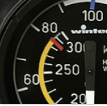
270 km/h
By default, 270 km/h is set as the highest speed (IAS, indicated airspeed), which the instrument specifies for the target flight. This must not exceed the maximum permitted speed for aircraft.
Caution: The default value should be checked and adjusted if the value in the flight manual deviates from the default.
Serial Interfaces
RS232 Interface S1

The RS232 interface is used to output the serial OpenVario data (TX) and as a serial to Bluetooth bridge (RX) to connect another serial device, e.g. a Flarm with the device on which XC Soar is running.
Baudrate

[Serial OFF]
[4800 baud]
[9600 baud]
[19200 baud]
[38400 baud]
[57600 baud]
[115200 baud]
Under this option, the speed can be set between 4800 and 115200 baud in the usual baud rates, or switched off [Serial OFF]. The interface is preset to the baud rate of 19200, which is also preset for FLARM. The speed setting always applies to both directions RX and TX. The default setting is perfect for normal operation of the FLARM to receive GPS data, baro and data from other aircraft. For regular downloads of longer flights, it is recommended to set a higher data rate. For example, with the data rate 57600, which is the highest supported by the Classic FLARM, longer flights can also be loaded in an acceptable time, which has proven to be stable in various applications. Tests on Power Flarms of the newer generation which support higher data rates also ran stably with 115200 baud. Of course, the higher data rate can remain the same for normal operation. The data rate must of course be set the same in FLARM.
Serial Loops
[Disable]
[Enable]
This option directs data from the receive direction of the serial interface to the send direction. The setting relates to the source of the data. For example [Enable] means routing of the data received on the receiving side (RX) to the transmission direction (TX).
The mode is only supported on S1, and is required, for example, if two devices are connected to an XCVario-20 device with only one interface, e.g. a FLARM on serial RX and an OpenVario on serial TX, and the data from the FLARM is also looped to the OpenVario should. However, this mode does not allow bidirectional communication with the respective devices, so no flight download from the Flarm and no synchronization of MC, ballast, bugs synchronization of XCSoar to the Vario is possible.
S1 Routing
With this setting, the data from all other interfaces can be routed to the serial interface S1.
The routing is always bidirectional, i.e. in addition to the sending direction, the receiving direction, i.e. the return direction, is also routed.
In the default setting for S1, the wireless interface is set to Enable, i.e. the coupled device is connected via WiFi or Bluetooth to a device on the serial interface S1.
This means that both the commands from the navigation device, e.g. from XCSoar, e.g. to control a radio device, and the messages that the device sends are routed back to the XCSoar.
The following figure shows the total of five interfaces of the router as they are named both in the setup menu and also here in the documentation.
XCVario
[Enable]
[Disable]
With this setting to “Enable” you select whether data of the XCVario should be output on the S1 interface and whether commands should be received and processed via this interface.
Wireless
[Enable]
[Disable]
This setting routes the data between S1 and the wireless interface, depending on the Bluetooth or WiFi setting. With this setting, the XCVario works as a Bluetooth or WiFi bridge and transparently forwards data from a wirelessly coupled navigation system with e.g. XCSoar to the serial interface S1. Data from other sources are switched to the interface one after the other using the time multiplex method.
S2-RS232
[Enable]
[Disable]
With this setting, the data is routed between S1 and interface S2 and vice versa. This is of interest, for example, if a Flarm is connected to S1 and an OpenVario is to be operated at S2. This setting supports, for example, the possibility of connecting a serial FLARM to S1 and an OpenVario to S2 on the main device.
CAN-bus

[Enable]
[Disable]
This setting routes the data between S1 and the CAN bus, e.g. if they are also relevant on the secondary display. For example, if a FLARM is connected to the front device and its data is routed there to the CAN bus, it can be routed to S1 on the second display so that the FLARM data is available, e.g. for an OpenVario on S1. In this case set this setting to Enable.
TX Inversion
[Normal]
[Inverted]
According to the RS232 standard with real RS232 levels, mostly realized by a dedicated level conversion chip, a negative logic is actually used. A logical one is represented as minus 15 volts and a zero as plus 15 volts. With the RS232 “TTL”, as is usual with most avionics devices (although rarely mentioned in the manual), there is this level conversion and not, the RS232 TTL levels used there are usually 0 volts for zero and plus 5 volts for a one . In order to send to an RS232 TTL device with the correct logic, the default [Inverted] should be left as is. Devices with real RS232 level converters (plus/minus 15 volt level) usually also understand the voltages 0 and 5 volts that the RS232 TTL supplies, but need 0 volts for a one and 5 volts for a zero, there the setting would be [ Normal] necessary. The voltages are actively limited at the input of the XCVario, so the XCVario can also process the higher levels.
If the setting is correct, the connected device responds correctly to commands sent and readable characters appear in the NMEA device monitor of the navigation system. The XCVario works with 3.3 volt levels, but external 5 volt hardware is compatible with it, since with the TTL standard the one is already reliably recognized from a level at the input of 2 volts, and 3.3 volts are significantly higher.
RX Inversion
[Normal]
[Inverted]
As with the TX (transmission) inversion but for the receiving side. Default is [Inverted] for RS232 TTL. Normally the setting is identical to the setting for the TX line. To check, look at the data in the XCSoar device manager, if readable ASCII characters appear there with the correct baud rate, the setting is correct.
Twist RX/TX Pins

[Normal]
[Twisted]
With this option, both a serial device with (DTE) interface, i.e. terminal such as FLARM, and a device with (DCE) i.e. modem or computer, such as an OpenVario, can be connected to the XCVario. In general, the following applies: With RS232 serial lines, a connection named TX at the other end must be switched together with a connection named RX. If the device at the other end is also labeled with TX on pin 4, then the XCVario turn the pins with the “Twisted” (or Swapped) setting to enable a connection with 1:1 standard patch cables. The normal setting means pin 3 = TX and pin 4 = RX. In twisted (or swapped) mode, pin 3 = RX and pin 4 = TX at the IGC standard end of the usual Flarm cable set connected S1, or directly at the IGC compatible S2 port.
TX Line

[Disable]
[Enable]
With the help of this option, the transmission line (TX) of the S1 interface can be switched off in the [Disable] setting. Then only the data arriving in the receiving direction of interface S1 (RX) is evaluated, the transmission line remains high-impedance.
The feature is required if two devices are to be connected to the external source (e.g. FLARM) using a simple passive 1:1 splitter (RJ45 T-piece) and 1:1 standard cable 8P8C is to be used. In [Disable] mode, the FLARM cannot be actively accessed from the XCVario, e.g. to declare a flight task or to download a flight.
Monitor
[Disable]
[Start S1 RS232]
Data monitor for S1 serial RS232 interface (same as in Wireless menu but shortcut for S1 RS232 in here). [Start S1 RS232] will start the data monitor a short press to the rotary button is to start/pause the monitor, a long press to terminate the data monitor.
RS232 Interface S2
The second RS232 interface, from series 2021, is primarily used for communication with a serial OpenVario data (TX) device, e.g. for an OpenVario or a serial Kobo, or in the case of a wireless device as a serial to wireless bridge to connect another device to the wireless to connect devices. Various devices are possible, various radio devices that your Navi supports, e.g. a KRT2 or ATR833 radio device (fixed baud rate 9600 baud) can be connected here.
Baudrate
[Serial OFF]
[4800 baud]
[9600 baud]
[19200 baud]
[38400 baud]
[57600 baud]
[115200 baud]
The baud rate is set in the same way as for Interface S1, the same baud rates are supported.
S2 Routing
With this setting, each of the four other data sources or sinks can be routed to the serial interface S2.
The default is via wireless: Enable, i.e. the coupled device, either via WiFi or Bluetooth, is brought together with a device on the serial interface S2. This means that both the commands from the navigation device, e.g. from XCSoar, e.g. to control a radio device, and the messages that the device sends are routed back to the XCSoar.
XCVario
[Enable]
[Disable]
With this setting to “Enable” you select whether XCVario data is to be output at the S2 interface and whether commands are to be received and processed via this interface.
Wireless
[Enable]
[Disable]
This setting routes the data on S2 to the wireless interface, depending on the Bluetooth or WiFi setting.
S1-RS232
[Enable]
[Disable]
With this setting, the data is routed from S2 to the S1 interface and vice versa. This is of interest, for example, if a Flarm is connected to S1 and an OpenVario is to be operated at S2. This setting supports the possibility of connecting a serial FLARM to S1 and an OpenVario to S2.
CAN-bus
[Disable]
[Enable]
This setting routes the data between S2 and the CAN interface, e.g. if they are also relevant on the secondary display.
TX Inversion
[Normal]
[Inverted]
Identical to the function as with S1, only here for the interface S2.
RX Inversion
[Normal]
[Inverted]
Identical to the function as with S1, only here for the interface S2.
Twist RX/TX Pins
[Normal]
[Twisted]
Identical to the function as with S1, only here for the interface S2.
TX Line
[Disable]
[Enable]
Identical to the function as with S1, only here for the interface S2.
Monitor
[Disable]
[Start S2 RS232]
Data monitor for S2 serial RS232 interface (same as in Wireless menu but shortcut for S2 RS232 in here). [Start S2 RS232] will start the data monitor a short press to the rotary button is to start/pause the monitor, a long press to terminate the data monitor.
CAN Interface
The XCVario-22 hardware from around October 2021 also has a CAN bus interface as an option for data transmission to a second device and for connecting future hardware. For devices without CAN, leave the settings at CAN-OFF as shown here in bold (default setting). The CAN bus supports cable lengths of up to 20 meters.
Datarate
[CAN OFF]
[250 Kbit]
[500 Kbit]
[1 Mbit]
The data rate can be set here. It is recommended to use the 1 Mbit setting, which works without problems over the short distance on the plane and is far outside the spectrum of the radio.
CAN Routing
With this setting, any data source or sink can be routed to the CAN bus. The routing is always bidirectional, i.e. in addition to the sending direction, the receiving direction, i.e. the return direction, is also routed.
The default is “Disable” for all data, because this only makes sense if a second display is to be connected and synchronized via the CAN bus.
XCVario
[Disable]
[Enable]
With this setting to “Enable” you select whether XCVario data is to be output on the CAN bus and commands are to be received and processed via the CAN bus. It assumes that the other party also routes the corresponding data to the CAN bus.
Wireless
[Disable]
[Enable]
This setting routes the data between the CAN bus and the wireless interface, depending on the Bluetooth or WiFi setting.
S1-RS232
[Disable]
[Enable]
With this setting, the data is routed between S1 and the CAN bus and vice versa. With this, for example, the data of a Flarm can be transmitted to S1 via the CAN bus to the second display.
S2-RS232
[Disable]
[Enable]
The same functionality as with “S1-RS232” visible here in the setup for the S2 interface.
Mode
[Master]
[Client]
[Standalone]
This setup is essentially relevant when two devices are connected to the CAN bus in a two-seater. “Master” must then be set for the front device and “Client” for the rear device. Otherwise the mode remains on “standalone” which is delivered by default.
Caution: If the mode master is selected for a standalone device, a dummy load is created by the traffic that is sent to the second device but not confirmed. The standalone setting is therefore optima
NMEA Protcols
NMEA Protcols
[OpenVario]
[Borgelt]
[Cambridge]
[XCVario]
[Disable]
This option is used to set the protocol of the data that the variometer sends ‘variometer data’ to the connected device via Bluetooth, Wifi or serial.
OpenVario

This is the default setting of the XCVario and offers the essential data of the variometer sensors such as the barometric pressure for the altitude, the dynamic pressure for the airspeed, TE Vario information and the outside temperature, provided the temperature sensor is installed accordingly. The synchronization of MC, bugs or ballast is not implemented by XCSoar and is therefore not sent.
The OpenVario (POV) protocol is defined as follows:
$POV,P,<baro>,Q,<dp>,E,<te>,T,<temp>“

Example:
P,1018.35:  1018.35 hPa barometric pressure
E,2.3 :            +2.3 in m/s vario climb
T,23.52:        23.52° OAT temperature in deg C
A detailed description of the protocol can also be found here: https://www.openvario.org/doku.php?id=projects:series_00:software:nmea
Borgelt

The second option is [Borgelt], ‘Borgelt B50/B800’ is to be set as the device driver on XCSoar. The Borgelt protocol $PBB50 supports the synchronization of MacCready value (MC), ballast or insects (bugs), from and to the XCVario. The barometric height is not part of the Borgelt protocol, but is transmitted via a generic interface using the $PTAS1 NMEA data set as height above the standard pressure area (1013 hPa). The QNH must therefore be set separately on the XCSoar and on the Vario, and enables, for example, a standard setting on the XCSoar and a QNH setting on the Vario, which can make sense for flights near airspace restrictions that are usually related to the standard .
Format see below, this format is also automatically sent to XCSoar and always evaluated there, regardless of the protocol driver set, as well as the standardized FLARM data.
The Borgelt datasets have the following format:
$PBB50,AAA,BBB.B,C.C,DDDDD,EE,F.FF,G,HH*CS<cr><lf>
AAA = TAS 0 to 150 knots
BBB.B = Vario, -10 to +15 knots, negative sign for sink
C.C = MacCready 0 to 8.0 knots
DDDDD = IAS squared 0 to 22500
EE = bugs degradation, 0 = clean to 30 %
F.FF = Ballast 1.00 to 1.60
G = 1 in climb, 0 in cruise, Note: Original Borgelt docu shows vice versa
HH = Outside airtemp in degrees celcius (may have leading negative sign)
CS = standard  NMEA checksum

$PTAS1,xxx,yyy,zzzzz,aaa*CS<CR><LF>
xxx: CV or current vario. =vario*10+200 range 0-400(display +/-20.0 knots)
yyy: AV or average vario. =vario*10+200 range 0-400(display +/-20.0 knots)
zzzzz: Barometric altitude in feet +2000, related to QNH standard 1013.25 setting
aaa: TAS knots 0-200
CS: XOR Checksumme
Cambridge

Using the Cambridge !W (CAI302) format, other devices can be supplied with data, for example LX-Mini-Map, LK8000 and others that only understand this format. The Cambridge format supports synchronization of MC, Ballast Bugs and QNH (QNH from device only), but no AHRS information. All relevant data fields are supported, except for the wind vector, which is calculated in the cross-country flight program. This format is available in the current software versions, so far as an experimental format and only tested with XCSoar, further tests for other devices are necessary.
* Cambridge 302 Format
!W,<1>,<2>,<3>,<4>,<5>,<6>,<7>,<8>,<9>,<10>,<11>,<12>,<13>*CS<CR><LF>

<1> Vector wind direction in degrees
<2> Vector wind speed in 10ths of meters per second
<3> Vector wind age in seconds
<4> Component wind in 10ths of m/s + 500 (500 = 0, 495 = 0.5 m/s tailwind)
<5> True altitude in Meters + 1000
<6> Instrument QNH setting
<7> True airspeed in 100ths of Meters per second
<8> Variometer reading in 10ths of knots + 200
<9> Averager reading in 10ths of knots + 200
<10> Relative variometer reading in 10ths of knots + 200
<11> Instrument MacCready setting in 10ths of knots
<12> Instrument Ballast setting in percent of capacity
<13> Instrument Bug setting
*CS Checksum, XOR of all bytes of the sentence after the ‘!’ and before the ‘*’
XCVario

For the XCVario with AHRS, a separate protocol with its own “XCVario” device driver was developed which combines the elements of the setup, the transmission of sensor data and the AHRS capability of the new series in the new protocol $PXCV. The protocol has already been adopted in the XCSoar project and is supported since releases (> 6.8.16). With the XCVario protocol, as with the Borgelt protocol, a bidirectional synchronization of MacCready value, ballast and bow as well as QNH (QNH only from the device) can be achieved, and the transmission of the AHRS sensor data for the position indicator (horizon) is also fully supported.
The protocol unifys basic components of the Cambridge CAI302, Borgelt, and the OpenVario protocol. The protocol also supports QNH synchronization. Series 2020 devices without IMU chip cannot supply the acceleration datafields.
The XCVario sentence has the following format:
$PXCV,

BBB.B, // Vario, -30 to +30 m/s, negative sign for sink
C.C, // MacCready 0 to 10 m/s
EE, // Bugs degradation, 0 = clean to 30 %
F.FF, // Ballast 1.00 to 1.60
 G, // 1 in climb, 0 in cruise, Note: Original Borgelt docu shows vice versa (bug in docu)
HH.H, // Outside airtemp in degrees celcius ( may have leading negative sign )
QQQQ.Q, // QNH e.g. 1013.2
PPPP.P, // Static pressure in hPa
QQQQ.Q, // Dynamic pressure in Pa
RRR.R, // Roll angle
III.I, // Pitch angle
X.XX, // Acceleration in X-Axis
Y.YY, // Acceleration in Y-Axis
Z.ZZ, // Acceleration in Z-Axis
*CHK = standard NMEA checksum
<CR><LF>
Disable
With this selection, all NMEA transmissions from this menu item are switched off, e.g. if no external device is present, or if only the NMEA data sets from other settings, e.g. only the data sets of the AHRS subsystem or the compass are of interest.
AHRS RAW
[Disable]
Enable
Option to send as well the RAW AHRS gyro and accelerator data the follwing format
!XCV,
G,<gx>,<gy><gz>, // gyro rotation deg/s in all 3 axis; Format %.3f e.g. 8.123 [°/s]
A,<ax>,<ay><az> // acceleration in multiple of G in all 3 axis; Format %.3f e.g. 1.522 [g]
*CHK = standard NMEA checksum
<CR><LF>
Logging
Logging
[Disable]
[Sensor Raw Data]
Default is [Disable]. The Option [Sensor Raw Data] enables beside normal NMEA protocol dataset’s the output all sensors data together with timestamps in a format as below. The data can be logged in XCSoar using NMEA Logger together with any other NMEA data that is sent or logged by the device.
Example: $SENS;91532;954;975.8;975.8;0.0;25.6;0.141;-0.049;0.988;0.000;0.000;0.000,-1858;3188;6466
| The format is: $SENS; <timestamp ms since start>; <time since last GPGGA fix received>; <BApressure in hPa>; <TEpressure in hPa>; <PIpressure in Pa>; <OAT in °C>; <AccelX in g>;<AccelY>;<AccelZ>; <GyroX in °/s>;<GyroY>;<GyroZ> [;<MagX in Gauss*8192>;<MagY>; <MagZ>] \n |
XCSoar

XC Soar is free open source software and can be installed on various systems, e.g. Android devices. These usually already contain a GPS receiver which provides sufficiently accurate GPS data for the current position or the speed over ground.
For a complete glider flight computer, however, further values such as dynamic pressure, TE nozzle pressure, static pressure are missing in order to be able to run a usable vario display or information for the cruise mode for the current speed to fly. The XCVario delivers exactly this data to XC Soar either wirelessly via WiFi or Bluetooth or a serial RS232 interface.
The XCSoar software runs on many platforms, including Android devices such as modern smartphones, e-book readers such as Kobo’s, Android navigation systems with bright color displays and large screens, as well as many Linux-based systems, including Raspbery-PI and an OpenVario.
Ready-made devices are available on the market with sufficiently bright displays and touchscreens and are well suited for use in the cockpit. With the XCVario, advanced technology is available at an affordable price. There are also OpenVario hardware suppliers who are just as well suited to be combined with the XCVario. Various users prefer the XCVario to the OpenVario’s native sensor box for various reasons.
In cruise mode, XCSoar can use the data from the XCVario to provide precise target flight information, and the wind calculation also works without any problems. All in all, XCSoar together with the XCVario offers a glider computer with the latest technology, intuitive touchscreen operation (on touchscreen devices), many screens full of features for thermal cranking, cruise mode, final approach with freely configurable info boxes, display of terrain with airspace including side view. Displays with topography and landing fields. There are also assistants for competitions, a vario with an acoustic function, speed command for MC or dolphin cruise mode and much more.
XCSoar Configuration

On the wireless device with XCSoar, e.g. tablet or smartphone, the XCVario can be integrated into the XCSoar application with just a few clicks. For this purpose, the device must have either Bluetooth or WiFi hardware on the hardware side. The XCVario will support both variants from December 2020.
Bluetooth

In order to establish a connection with Bluetooth, the XCVario must be set to Bluetooth in Setup/Options/[Wireless iVario-123]. This is the default.
First, the XCVario must be paired with the Android as a Bluetooth device.
To do this, perform a device scan in the Android device setup under Bluetooth, and first pair the Vario, which should appear there as XCVario-5678, for example, in the pairing dialog. The number (only three digits for the 2020 series) is the serial number of the device.
If a Bluetooth password is requested for older devices, this should be entered with “1234”.
Then in XC Soar under Configuration/NMEA connection, a previously free connection A..F is to be set up (edit). If the XCVario is paired via Bluetooth, it can be found in the ‘Connection’ field with its Bluetooth ID, e.g. XCVario-5678. Select this there and in the following dialog enter the desired driver, for current XCVario versions “XCVario”. The switch K6Bt remains in the ‘off’ position. After acknowledging the dialog with “OK”, XCSoar will connect to the vario within a few seconds, which will then appear as a regular NMEA connection, e.g. with the status “connected; Baro,Vario” is displayed.
The relevant records of the Vario should now be visible under ‘Monitor’, more details on this under Device drivers below. Only one device can be paired with Bluetooth at a time. Unfortunately, this is a limitation of the Bluetooth/RFCOMM protocol, and cannot be changed.
Wireless LAN
In order to set up a wireless LAN connection (also called wireless LAN, WLAN or WiFi), the XCVario must be set to wireless LAN in Setup/Options/[Wireless XCVario-1234]. If this is the case, you can register a wireless device, e.g. an Android device, on this WLAN. The network ID is identical to the Bluetooth ID, e.g. XCVario-5678. Pairing with WiFi is done by entering the password.
The WLAN password is: xcvario-21 all lowercase and with a hyphen (minus sign).
The XCVario is a pure data device and of course does not offer an interface to the Internet, which causes some devices to constantly search for better networks and, if successful, to switch to them.
In order to ensure a secure connection, for example if the Android device switches to WiFi when starting the clubhouse, the passwords for other WiFi networks should be deleted on the device for security reasons, or these networks should be deleted from the device or, if supported, these on the device be blocked.
While it is not possible to specify a second device driver with Bluetooth, this is possible when connecting via WiFi through different ports. The ports are permanently assigned to the interfaces in the Vario (see also the overview at the beginning of the document). It is also possible to connect up to 3 devices at the same time via WiFi. Two devices are possible without any noticeable loss of performance. The limitation in the software is 4 devices.
The XCVario offers a total of three ports for different drivers on one IP address.
The “TCP Client” option must be selected for the device connection, the IP address must be specified as 192.168.4.1 (the IP address of the server) and the ports assigned as shown in the following chapter.
XCVario TCP Ports
| 8880 | XCVario sends sensor data according to the device driver set under NMEA protocol in the Vario |
| 8881 | FLARM if a FLARM is connected to the connector of the FLARM cable (connection S1-RS232), the data is exchanged on this port. |
| 8882 | From the XCVario Series 21, another device, e.g. a radio, can be controlled via this port on the second serial interface S2. |
The Vario forwards the data to the device via its internal router. Here, the routing to “Wireless” must be activated on the corresponding serial interface. Details on the setting in the Router section, in the setup for wireless routing, and the RS232 interfaces.
Device driver
There are several device drivers on the XCVario device setup page, more details on this in the previous chapter on setup under Setup/NMEA protocol. To help you decide, here are a few explanations.
OpenVario
So far, all devices have been delivered with the default setting OpenVario. This protocol does not support any setting from or to the device, which is sufficient for many users or even desired, e.g. a security MacCready value should be set in XCSoar in order to receive information there for a safe arrival at the destination, and ballast or settings for Bugs are not an issue and the real-time display of the XCVario is used for the speed to fly. In the future, delivery will take place with the XCVario protocol.
OpenVario data example:
$POV,P,978.1,Q,0.0,E,-0.0,T,15.0*4F
Borgelt
In order to enable an exchange of settings, which some users want, the Borgelt B50/B800 protocol was already implemented during the 2020 season (from software version 20.0815-21). This allows MC, ballast and bugs to be synchronized in both directions, but not QNH, since this is not part of the Borgelt protocol.
But you don’t necessarily need the altitude display on the XCSoar, and you can read the easy-to-read altitude value on the XCVario, in which case synchronization is not necessary. If you also want the altitude to be displayed in XCSoar, set the QNH on both devices before takeoff.
Since the Borgelt does not support barometric altitude, an additional sentence is sent in the NMEA standard protocol “PTAS1” after each Borgelt sentence. XCSoar automatically evaluates standard NMEA sentences, which also transmits the altitude to the XCSoar flight computer.
Borgelt data example:
$PBB50,000,+0.1,3.7,0,0,1.00,0,25*65
$PTAS1,+0.1,+0.0,+3000,0*34
Cambridge
This protocol was not developed with XCSoar in mind, but rather for end devices with a navigation program (Oudie, LX) which neither Borgelt nor XCVario supports. Basically, it doesn’t offer much of an advantage over Borgelt. A synchronization of MC, ballast and bugs from the XCVario is thus possible in the same way. The XCVario transmits the true airspeed (TAS), altitude, variometer values and the QNH setting. If the connected device supports it, these values (except for QNH) can also be synchronized in the XCVario direction. Borgelt also uses the Cambridge protocol for these settings.
XCVario

The above variants have no way of transmitting information from the gyro sensor. Although there are some protocols that could do this (e.g. Eye-Sensorbox), any settings fall by the wayside. Something new therefore had to be developed for the 2021 series.
Today, the XCVario is delivered with the XCVario setting by default.
The new “XCVario” driver has been integrated in the last 6.8 versions and in the 7 versions of XCSoar (update via Google Playstore) since the 2021 season. In addition to the entire sensor system, including the AHRS position sensor, the XCVario protocol also supports the exchange of all settings, including QNH from the device in the direction of XCSoar. The QNH setting from XCSoar to the device is currently not possible, but is already supplied in the source code and is expected from version XCSoar 7.22.
XCVario data example:
$PXCV,-0.0,0.5,0,1.00,0,24.4,1012.0,962.0, 0.0,0.1,-3.2,-0.05,0.00,0.99*1C
XCVario commands:
The XCVario protocol supports various NMEA commands for setting, the first three are used to set the MacCready value and ballast and bugs and correspond 1:1 to the Cambridge format line termination. The commands for QNH and the speed-to-fly mode were based on the Cambridge data format, also contain a checksum, and continue to follow the NMEA standard, i.e. they are terminated with <CR> and <LF>. These enable the remote control of the XCVario, e.g. via XCSoar controlled “sendNMEA1” events that can be defined in an .xpi file, e.g. controlled by an XCNav or Stefly remote stick.
In addition, the landing gear warning can be triggered and stopped again via a command from an external device.
The following commands are supported at the moment:
Installation
The XCVario has been kept simple in terms of installation and configuration. The installation in the cockpit is therefore easy.
Rear panel Connections
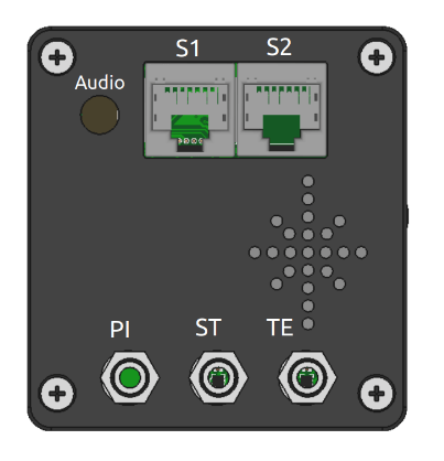
The connections are shown on the right. Except the first series out of 2020 that features only the left RJ45 connector the S1, all recent devices feature two electrical RJ45 connectors S1 and S1. The pin assignment, see the chapter on the RJ45 connectors. The interface S2 has standard IGC assignment, the connection of individual XCVario supplied devices such as the flap sensor or the magnetic sensor and can be done on S2 with 1:1 patch cables. The 80 mm variant has the same rear connections.
Caution: All other devices must be connected via the S2 extender/splitter. A direct connection of a Flarm, for example, to S2 can damage the CAN bus (from XCVario-22).
The supplied wiring harness may only be connected to the S1 socket with the “Vario” labeled plug. Do not connect the Vario plug to the S2 socket either. If voltage is present, this can damage the temperature sensor in the cable on older revisions of the wiring harness.
Also, do not connect the end of the wiring harness that is labeled “Flarm” to the XCVario, this is intended for a Flarm IGC port and should remain unused if Flarm is not used.
Please also note that a possible defect caused by demonstrably faulty wiring is not covered by the warranty.
Pneumatic connections
The pressures required for the XCVario can be connected to the instrument hoses of the mechanical instruments using 6 mm T- or Y-pieces. If these connections are not already available from a previous Vario, the instrument hose can be cut at a suitable point and the connection for the Vario can be made using a T-piece.
Note: A compensation vessel as usually equipped in older installations is NOT needed. Do not connect this to any of the pressure hoses of the XCVario.
You will need:
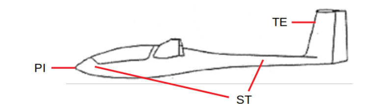
TE:  TE-probe pressure

ST:  Static pressure ( = Static )

PI:  Total Pressure ( = Pitot = overall pressure )
The pressures are usually hosed by the manufacturer behind the instrument panel, and are either already routed there, and can be taken over 1:1 from from a previous device, or can be taken from mechanical instruments using a simple pneumatic T-piece. The pressures for PI and ST are on the airspeed indicator, the TE pressure usually on a mechanical variometer.
Electrical connections
Micro USB
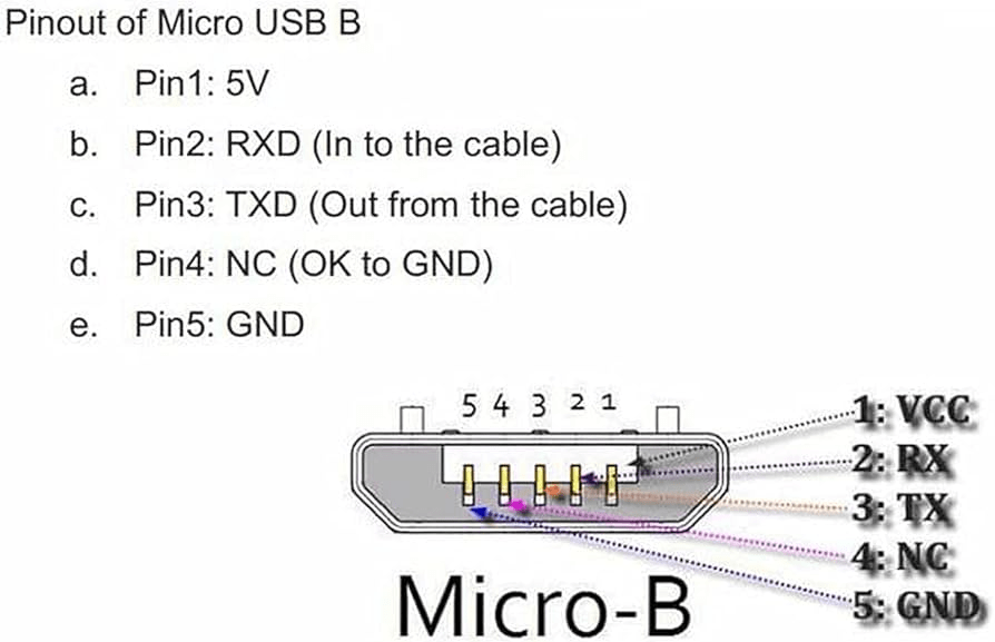
The device is programmed for the first time in the factory via the Micro USB-B connector on the sensor circuit board and is only accessible in the 20 and 21 series when the cover is removed. From the 22 series (57 mm), the USB-B connector is accessible on the top of the device, the opening is sealed with a sticker at the factory. The cable can only plugged in one position, the wider section of the connector is towards the front.
The device can be connected to a PC via USB for diagnostics and can also be supplied with power via the PC. In order to establish contact with the serial interface of the ESP32, drivers for the serial USB converter chip CH340G may be required.
The connection is not required for operation as a variometer, nor for the OTA software update, which takes place via the ESP32 OTA WiFi connection.
Audio Output
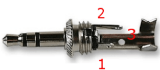
A 3.5mm stereo jack offers an external output for the audio signal of the variometer. Either your own external speaker can be connected to it, or an audio input of a radio device can be used. Normally, the internal loudspeaker of the variometer is sufficient, but it can make sense to be able to hear the signal there, e.g. when operating with headsets, or to connect an external loudspeaker closer to the head in loud cockpits. The internal speaker switches off if an external audio device is plugged in.
Abbildung 1: Audio Stecker The picture on the right shows the necessary audio plug, it is a standard 3.5 mm jack plug with tip, ring, sleeve (TRS), i.e. 3 connections. In the model in the drawing on the right, connector 1 is the tip, 2 is the ring, and 3 is the sleeve. The speaker is connected to connection 1 and 3. Port 2 remains unassigned (NC). If in doubt, measure the connector with a multimeter. The speaker must be connected between the tip and the ground pin.
| Anschluss | Bezeichner | Lautsprecher |
| 1 | Tip, L | connection 1 |
| 2 | Ring, R | NC |
| 3 | Sleeve, GND, Mass | connection 2 |
On the Vario side, the mono audio signal is also applied to connection 2 (ring), so it is not possible to use a mono jack plug (TS) with devices from the 2020 and some 2021 series, as this does not have an isolated ring between connection 2 and 3, and connects connection 2 to ground. From the 4/2021 series, i.e. devices from September 2021, the Vario signal is only output on connection 1, the alternative use of a mono plug is then possible.
RJ45 connector S1
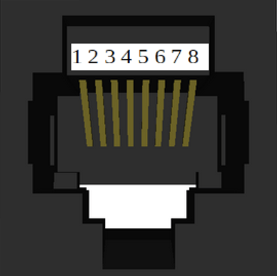
The standard shippment includes a cable tree the XCVario FLARM cable that features a ready-made temperature sensor, a plug for standard applications (standard IGC assignment, e.g. as with most FLARMs and loggers), and an open cable end for a S2F switch. The cable can also be obtained from the shop.
Caution: The assignment at connection S1 with S2F switch and temperature sensor does not have an IGC assignment but is XCVario-specific and different from S2. The XCVario FLARM cable converts the assignment on the S1 appropriately, so that the IGC standard assignment (RJ45) required for the FLARM is available at the end of the FLARM cable. The RJ45 socket is shown in the figure above in a plan view from the rear. Pin 1 is therefore on the far left. The minimum connections required to operate the device in its basic function are shown in bold.
Interface S1
| Pin# RJ45 FCC | Pin# RJ45 IGC | Identifier | Direction | Cable colors 568B |
| 1 | 8 | Plus 8..28 VDC | Power In | orange-White |
| 2 | 7 | RS232 TTL RX | Signal In | orange |
| 3 | 6 | RS232 TTL TX | Signal Out | green white |
| 4 | 5 | Vario/Speed to Fly Switch | Signal In | blue |
| 5 | 4 | T-Sensor +3.3 VDC | Power Out | blue White |
| 6 | 3 | T-Sensor Data | Signal Out | green |
| 7 | 2 | GND | Power In | brown-white |
| 8 | 1 | GND | Power In | braun |
Temperature sensor
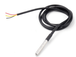
The temperature sensor must be connected to the three pins 5, 6 and 7 provided with the RJ45 cable of the corresponding color. The temperature sensor is part of the FLARM cable.
The temperature sensor is a ready-made Dallas DS18B20 sensor with a waterproof casing and a 1 meter long cable. The sensor has three colored lines, which are usually coded with the colors red, yellow and black. If you use your own sensor, the manufacturer’s instructions must be observed.
The shipped cables comes with this sensors or can be ordered in the shop. To measure the outside temperature, the sensor is to be placed e.g. in the front vent.
This can also be done in the ventilation pipe if available. In this case, a small slit is cut with a cutter knife, the temperature sensor is pushed in and sealed with aluminum adhesive tape or silicone, for example.
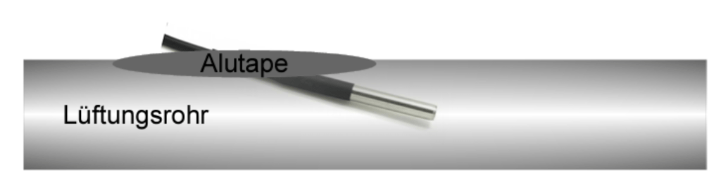
Speed to Fly switch:
The vario/speed command switch is to be connected to pin 4 of the RJ45 and to ground pin 8. If the switch is closed, target travel is selected. The function can also be changed in the setup, i.e. when the switch is closed, Vario mode is selected.
S1 Serial (FLARM plug)

The FLARM is the standard configuration for the Interface S1 and can be connected to the XCVario with the standard FLARM cable at FLARM plug labeled ending. With the simple FLARM cable, only the direction FLARM is connected to XCVario (Series 20), i.e. only pin 4 in FCC numbering. These cables are no longer offered. The bidirectional FLARM cable is required for bidirectional communication with the FLARM (standard from series 2021). This enables e.g. the flight declaration in FLARM via the navigation system (e.g. XCSoar).
Below is the assignment at the FLARM end of the standard cable, the minimum connections required for receiving FLARM data are shown in bold.
| Pin# RJ45 FCC | XCVario FLARM Cable End | FLARM with RJ45 Interface |
| 1 | GND (orange/white) | GND |
| 2 | GND | |
| 3 | RS232 TX (green/white) | RS232 RX |
| 4 | RS232 RX (blue) | RS232 TX |
| 5 | ||
| 6 | ||
| 7 | +8..28 VDC | |
| 8 | +8..28 VDC | +8..28 VDC |
RJ45 connector S2
From series 2021, the hardware has the second electrical RJ45 connector “S2” with standard IGC assignment for the serial port, plus an additional input/output for a flap sensor and for a CAN bus (2).
A Strefly OpenVario, a FLARM in various versions, a Volkslogger, a radio device or any other device supported by XCSoar can be connected to the serial interface, pins 3,4 with a 1:1 patch cable. If the connected device does not have a standard IGC RJ45 plug, this should be done with a specially made specific cable. There are sources on the Internet for various devices. A customer-specific cable can usually be made by yourself according to the requirement, XCVario provides support for this. All connections on the S2 are optional for stand-alone operation of the device.
Interface S2
| FCC Pinout RJ45 | IGC Pinout RJ45 | Identifier | Direction | 568A | 568B | Connection |
| 1 | 8 | GND | Power In | grün-weiss | orange-White | Bordnetz Masse |
| 2 | 7 | GND (1) | Power In | grün | orange | – |
| 3 | 6 | RS232 TTL TX | Signal Out | orange-weiß | green white | Navi Serial RX |
| 4 | 5 | RS232 TTL RX | Signal In | blau | blue | Navi Serial TX |
| 5 | 4 | CAN-L (2) | Signal Out | blau-weiß | blue White | – |
| 6 | 3 | analog input | Signal In | orange | green | 0 ..1.2 volt voltage against GND |
| 7 | 2 | CAN-H (2) | Signal Out | braun-weiß | brown-white | – |
| 8 | 1 | +8..28 V | Power In | braun | braun | electrical system +12V DC maximum 500 mA power output |
(1) From series 2021/2 available since June 2021
(2) From series 2021/3 available since October 2021
S2 Serial (Device)
Standard configuration for S2 is a serial device such as Kobo, serial OpenVario, a radio or else. The Pins are according to the IGC standard, hence a 1:1 cable is only recommended for devices that do not have any connection on the other pin’s except GND and on power pin. Other devices shall be connected via the S2 Extender/Splitter that only connects the serial pins, power and GND.
Analog Input (flap sensor)
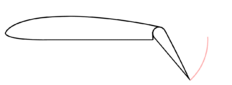
Except the first serieas of 2020, the XCVario features an analog input for various functions. The major application of this input is usage with the flap sensor. Its also usable as a gear alarm input alternatively (see gear warning chapter).
The flap sensor is available in the shop, and is to be mounted in a suitable position near the flap linkage and must be fixed to the fuselage wall with an appropriate holder e.g. with 5-minute epoxy, and attached to the flap in order to get a rotation of the shaft by an adhesive joint on the flap linkage. Under no circumstances should the linkage be drilled into.
Note: The analog input can only be used in Bluetooth mode due to a limitation in the first series 2021. For applications that require WiFi mode, the hardware will be required from March 2021.
CAN Bus
The XCVario-22 hardware features a CAN bus interface as an option for data transmission to a second device and to connect additional hardware such as the CAN magnet sensor.
External Devices
Stefly OpenVario
The Stefly OV can be connected to the XCVario directly at ttyS1 or ttyS2 with a 1:1 cable at S2 or with the FLARM of the standard cable at S1. The XCVario is fed directly via the OpenVario. Supplying the OpenVario with power from the XCVario is not recommended, because the OpenVario with its large display and higher power consumption is better suited as a supplier. In this case, the power supply (connection to the vehicle electrical system) of the XCVario at connector S1 remains unused. If you want to supply the two devices separately, which can make sense in order to switch them off individually in the event of a power shortage, or to protect each device with its own fuse, the +12V connection in the patch cable must be disconnected, and the XCVario supply must be disconnected from the power cables to be executed at S1.
Another option is to use the ttyS0 on the OV, in this case the RX and TX pins on the Sub-D connector of the OV, as well as ground, must be connected to the serial interface of the XCVario at S1 or S2.
The RX/TX pins on the variometer must be set to “Twisted” for this application in “Setup/System/RS232 Interface S[1|2]” under “Twist RX/TX Pins”. The default here is “Normal”. The baud rate must be set the same at both ends. All other serial interface settings remain unchanged.
The Flarm can be plugged directly into the OV, or it can be forwarded to the OV via the Vario. See also the settings for routing on the two serial interfaces. The pins shown in bold are the minimum necessary to display the data from FLARM on the OV.
| FCC Pinout RJ45 | IGC Pinout RJ45 | XCVario S1 FLARM or S2 | Stefly OV ttyS1 ( o. ttyS2) |
| 1 | 8 | GND | GND |
| 2 | 7 | NC | GND |
| 3 | 6 | RS232 TTL RX | OV TX |
| 4 | 5 | RS232 TTL TX | OV RX |
| 5 | 4 | – | – |
| 6 | 3 | – | – |
| 7 | 2 | – | +8..16 VDC |
| 8 | 1 | +8..16 V | +8..16 VDC |
As a cable to the OV, XCVario recommends an RJ45 standard cable 8p8c, i.e. 8pin with 8 connections, with assignment 1:1, as is often used in network technology, search for the following term on google or amazon: Flexible Network Cable Patch Cable.
As a rule, a length of 0.5 meters is sufficient between the two devices on the I board.
Caution: Wiring with an XCVario-22 to the OV always requires the S2 splitter, as the OV also supplies +12V on pin 7 and the CAN bus can otherwise be damaged (no guarantee if an OV is connected directly to S2). The OV is connected to the RS232 splitter port. If the +12V supply to the OV is to be completely suppressed, the Y-piece must be inserted and both jumpers for pin 7 and 8 pulled there in order to only establish the data connection between the two devices.
With two XCVarios and two OVs in a double-seater, the hoses only need to be connected to the front device, the data from the front device can be forwarded to the second device via the CAN bus.
To do this, the splitter is connected to S2 on the front device. The patch cable from the front device to the splitter should not exceed 50 cm in length, the shorter the better to rule out interference. The second device can then also be connected to the CAN port of the splitter via S2 with a patch cable of the appropriate length. In this case, the supply runs via the patch cable from the first device and therefore does not have to be wired explicitly for the second display.
The cables should be as flexible as possible so that no great forces are exerted on the plugs, and no longer than necessary for the connection.
Another flap sensor can be connected to the splitter, and with the help of an additional 1:1 RJ45 Y-piece on the CAN bus after the splitter, a CAN magnetic sensor is also possible.
KRT2
XCVario Interface Setup
The connection to the radio of the type KRT2 makes sense if your navigation device has a driver for it (XCSoar and LK8000 do so), can be established by a serial connection with any XCVario model that features a S2 interface on its back (all do except XCVario 20). The baud rate should be set to 9600 baud (the only one KRT2 supports = fix), and Routing settings need to enable only that interface your navigation system resides usually Wireless or S2-RS232. Everything else in the S2 setup remains on default.
Attention: If the setting for S2 routing are not correct, data not dedicated to a KRT2 might be routed to your radio resulting in transmission breaks and other odd behavior. Please ensure all other sources to be disabled in the routing settings, esp. S1-RS232 (is there is a Flarm), and XCVario.
Wiring KRT2
To connect the serial interface of your KRT2 make the connection from S2 pin 3 and 4 to the corresponding serial RX/TX of the KRT2, it is best to solder it there to the existing KRT2 Sub-D connector, to pin 2 and 13, crossed, i.e. RX from vario to TX of radio and vice versa as follows:
XCV 3 (TX)      <-> 13 KRT2 (RX)
XCV 4 (RX)     <->    2 KRT2 (TX Remote)
XCV 1 (GND) <->    1 KRT2 (GND)
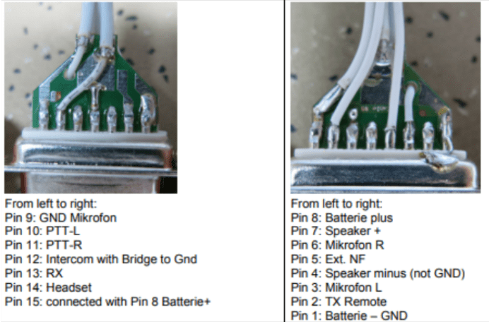
The software connection with the XCVario is only possible in WiFi mode (which may have a few disadvantages, see the Wireless LAN manual), via the TCP client with port 8882. Configure the driver for the KRT2 in the navigation system there.
Unfortunately, a connection via Bluetooth is not possible aside of XCVario because XCSoar can only configure one driver for an interface and only one Bluetooth connection to a device is possible. Alternatively, to stay with Bluetooth, there is the option of connecting the KRT2 to the XCSoar as a separate BT device via an external Bluetooth bridge. BT bridges are available from many manufacturers, or here in the shop: https://xcvario.com/product/serial-bluetooth-WiFi-adapter/
Using External Audio from KRT2

The XCVario has a highly efficient digital amplifier with pulse-width modulation that does not relate directly to ground, but rather emits a symmetrical signal (2). If you connect both poles of the audio out to the asymmetrical KRT2 radio input, one output suffers a short circuit to ground, what even can cause damage of the audio driver stage in prolonged operation, and high frequent noise. Do also not try to connect just one pin, and leave the other open, there will be noise as this is an invitation for disruptions: a ground loop across the supply lines. To get from a symmetrical output to an asymmetrical input, a small audio isolation transformer helps, which is available in small format for little money, for example here: https://www.ebay.de/itm/394922853247. Or here with cable ends: https://www.thomann.de/de/neutrik_nte_4_audio_uebertrager.htm . One side of the transformer is then connected to the two lines of the jack on the XCVario, e.g. on the Neutrik Yellow/White and the other side is between pin 5 and GND on the KRT2 (red/black).
ATR 833 Radio
The pin assignments and connections on the ATR833 are as follows, the corresponding driver is labeled ATR833 in XCSoar.
XCV 3 green/white (TX)        <->    9   ATR833 (Data RX)
XCV 4 blue (RX)                          <->  22  ATR 833 (Data TX)
XCV 1 orange/white (GND) <-> 25  ATR 833 (GND)
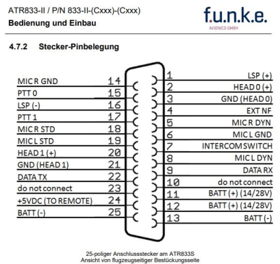
ECW100 (Flarm/GPS)
The ECW100 Flarm might be connected to the FLARM labled plug ending at S1 cable tree to the PC labled connector at ECW100. If a driver is needed for flight upload, FLARM is to be selected. For the GPS data there no driver required, GPS is standard NMEA and processed be XCSoar in any case. The connections are as follows:
XCV 3 green/white (TX)          <->    11 ECW100 (RX)        (3 PC RS232)
XCV 4 blue (RX)                            <->   12  ECW100 (TX)        (2 PC RS232)
XCV 1 orange/white (GND)  <->  13 ECW 100 (GND)    (5 PC RS232)
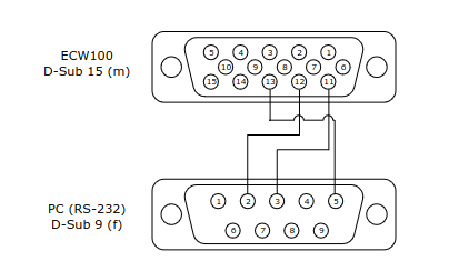
Source: Installationshandbuch ECW100 V1.6 pdf
Power Supply
The power supply is connected to the vehicle electrical system. A single fuse for a variometer is not mandatory for gliders, but is recommended. The wiring can be done with copper strands from 0.14 mm², 0.25 mm² is recommended. Alternatively, the XCVario can be connected in parallel to another device that is fused with at least 0.5, better 1 ampere. The device must be protected because the plug and cable are not designed for higher currents. The device tolerates voltages in the range of 5-28 volts, a supply of 12 volts is ideal. If the device is operated without any protection plus an external short circuit, e.g. at S2, internal damage is to be expected which is not covered by the guarantee. It is therefore essential to also secure it on the laboratory bench for test purposes.
The XCVario is protected against polarity reversal and is internally protected against transient overvoltages such as ESD discharges and induction peaks when starting. In general, the avionics should be left switched off when starting, if it cannot be avoided, e.g. when starting during the flight, you have to rely on the overvoltage protection.
Vario / Speed to Fly Switch
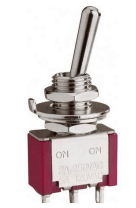
The vario S2F switch can be attached to the stick or in the instrument panel. Its second pin must be connected to ground (negative pole supply). With ground contact at pin 4, the vario is in speed to fly mode, with an open switch in vario mode. The speed command display is constantly in operation, but the tone generator changes to speed command as input. A button can also be used instead of a switch. In this case, the switch type must be set accordingly in the setup.
The switch is not absolutely necessary, as it is possible to automatically switch over to S2F from a certain speed. This can be achieved in the Audio/AudioMode menu with the “Autospeed” setting. The “AutoSpeed” is the speed above which the variometer switches to the S2F mode.
Serial RS232 Connections
The RS232 interface’s at the connectors S1 and S2 are used to connect a device without wireless (Bluetooth or WiFi) support, e.g. legacy OpenVario, older Kobo, or to connect a serial FLARM IGC port to the XCVario.
With a bidirectional cable (RX and TX direction connected), a flight task can also be declared in FLARM, the FLARM can be managed from your Navi App, or a flight download can be carried out. For the cable, see the description in the chapter on cable assembly. The FLARM application is preset, no settings need to be made on the serial interface in the setup.
In principle, only one device can be connected to one serial interface port. This is a limitation coming from the RS232 protocol. Analogy: One teacher can talk to multiple students at the same time, but only one student may as a question. There are tricks to connect multiple devices to one RS232 port, e.g. the second device does not have wired the transmission direction (TX) towards its peer, it can be connected in parallel. This may require special cables or adapters which not all have connections and do not connect the TX wire from the peer.
In the case of an OpenVario on the serial interface, the “XCVario” data is needed on the serial interface, which can be set in the setup of the “RS232 Interface S1” under “TX Routing”. More information in the setup description.
Pinout in IGC- and FCC Standard’s
The pins of the RJ45 sockets are numbered in the document according to the international standard of the Federal Communications Commission (FCC) in the usual way as numbering takes place all over the world. Beside this, the IGC (International Gliding Commission) standard for interfaces for reading out loggers did it their way (reversed). The XCVario’s S2 interface follows the IGC standard exactly, but document uses primarily the standard FCC numbering and may show IGC pin numbers beside that either for comparison in an extra column.
FCC-Standard:
IGC-Standard (pins incorrectly swapped):
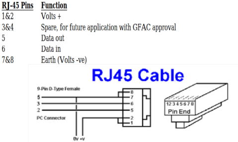
First Figure above shows the FCC standard, which designates the first pin in the top view of the connector as pin 8. Below here you see the reversed numbered IGC standard (source: TECHNICAL SPECIFICATION FOR IGC-APPROVED GNSS FLIGHT RECORDERS – Second Edition with Amendment 6 25 November 2020). There the numbering of the first pin on the connector on the left begins with pin 1 (!).
When verifying a device’s pin assignment, it is essential to always cross-check the pin numbers with the corresponding diagram. In the IGC standard, the numbering on the RJ45 plug (right) is correct. However, the pin numbering on the RJ45 socket (left) is incorrect. The table is valid only for the plug that is looked at the front with the cable running away from the observer so the “RJ45 Pins Functions” table above is correct — just for the plug, not for the socket. This is easy to confirm: If you were to insert the RJ45 plug shown above into the socket on the right, pin 8 would align with pin 1, which is clearly incorrect.
In summary:
- The plug is numbered correctly, the table is valid for the plug as shown.
- The socket is incorrectly numbered, pins on the lower side should be labeled 7&8 instead
The IGC’s reversed numbering for the socket and table, which differs from the FCC standard, causes confusion in many cases. Globally, manufacturers follow the FCC standard when numbering components, CAD symbols, and cables. Even avionics equipment manufacturers, who initially adopted the mirrored numbering from the IGC socket, have since reverted to using the correct FCC-standard pin assignments in their connector descriptions. The result of this inconsistency, especially the incorrect table, is that you cannot reliably determine whether a pin assignment is correct based on the pin number alone.
To avoid misinterpretation, a connector drawing that includes both pin numbering and signal names—from the same source—must always be referenced.
Comparison of the pin numbers of the FCC and the (wrong) IGC standard:
| Signal | RJ45 FCC Standard Pin# & IGC Standard Plug Pin# (right) | RJ45 IGC Socket false Pin# |
| Volts + | 7+8 | 1+2 |
| Data out (TX) | 4 | 5 |
| Data in (RX) | 3 | 6 |
| Earth (GND) | 1+2 | 7+8 |
Installation and drilling plan
The 57 mm device (left) corresponds mechanically to the aviation standard for instruments with a diameter of 57 mm, the 80 mm device to the installation dimensions for 80 mm instruments. The holes for four M4 instrument screws should be at least 4.5 mm. The instrument screws must not protrude more than 10 mm into the housing. There is no guarantee of error-free operation if screws > 10 mm are screwed in by force. Depending on the thickness of the instrument panel, screws from M4x8 to a maximum of M4x10 are recommended. The exact dimension of the drilling circle for the mounting screws is 66.675 mm for the 57 mm device and 89.095 mm for the 80 mm device.
In the case of particularly thick instrument panels with a thickness of more than 2 mm, a small, preferably semi-circular niche with a width of 2 mm and a height of 14 mm must be created halfway up the side for the rotary button. Normally this is not necessary, since standard panels are approx. 2 mm thick.

The 57mm device was developed for a 57mm bore and is optimally adapted for it. The 80mm device is more suitable for an 80 mm cut-out.
The installation of the 57 mm device in an 80 mm cut-out is still possible using our cover with threads and four shortened M4 screws or M4 screws and cap nuts on the front. The bezel is fastened as shown in the sketch with M4 countersunk screws from the back of the I-Panel (apply countersinks), against cap nuts on the front. Alternatively, normal M4 instrument screws can be screwed in from the front and then the overhangs can be trimmed flush at the back with a saw blade, or the screws can be cut to length beforehand to suit the strength of the I-board plus the panel. A corresponding cover with threads in the 89 mm bolt circle is available in the shop.
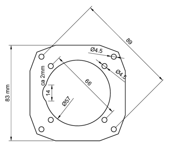
Drawing of the front part
The exact dimensions of the front part as interface to the instrument panel is shown below. The device is slightly asymmetrical towards the bottom, there is about 4 mm more space to be provided. If that is not possible, the device can also be turned 180 degrees, and the display can be rotated via the setup.
57mm device:
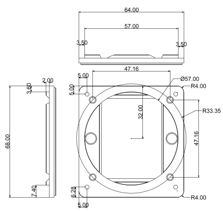
Technical Specification
| Power supply | 8-28 V DC |
| Voltage recommended | 10-18 V DC |
| Current consumption at 12.5V typical | 70 mA = 0.9 Watt (idle) 100 mA =1.2W (Wireless connected) 120 mA =1.5W (XCV-23, heating on) 250 mA = 2.5W (max Volume) |
| Bluetooth Standard | V4.2, EDF, classic Bluetooth |
| WiFi Standard | 802.11 b/g/n Wi-Fi MAC Protokoll |
| Variometer range | +- 1m/s bis +-30m/s |
| Baro and TE pressure sensor resolution | 0,01 hPa (0,1 m) |
| Baro sensor relative accuracy | 0,12 hPa (1 m) |
| Baro sensor absolute accuracy | 1 hPa (8 m) |
| Barometer range | 0-9.000 m calibrated until 16.000 m uncalibrated |
| Dynamic pressure sensor accuracy at 100 km/h | 1 km/h |
| Dynamic pressure sensor area | 10 – 280 km/h |
| Temperature sensor area | -10..85 °C |
| Temperature sensor accuracy | +-0.5 °C |
| Case dimensions (width x height x depth) | 64x68x35 mm (5) 80x80x35 mm (8) |
| Section in the instrument panel | 57 mm (5) 80 mm (8) |
| Electrical connection | 2x RJ45 Main socket 8 pin |
| RJ45 / RS232 Interface S1 | RS232 RX/TX (TTL level 3.3V) |
| RJ45 / RS232 Interface S2 (IGC Standard) | RS232 RX/TX, CAN Bus, Analog In 0..1V |
| RJ45/ OneWire Interface | OneWire bus interface for temperature sensor with 3.3V power supply (470 ohm series resistor for short-circuit protection) |
| CAN Interface (2) | 250 kBit..1MBit CAN Bus |
| USB Interface | Micro USB-B |
| Audio output | 2 watt power (3) 3.5 mm stereo jack switched, disables internal speaker |
| Pneumatic connections | Three 6 mm nipples for PVC hose 8×1.5 mm (5 mm inner diameter) |
| Weight | 165 g (5) 235 g (8) |
(1) From 2021 series hardware
(2) From series 2021/3 (October 21)
(3) 2020 series with 1.2 W power
(5) 57mm Modell
(8) 80mm Modell
Maintenance
The variometer itself does not require any further maintenance, since a regular leak test of the instrumentation is normally required as part of the maintenance program (IHP/AMP) of the aircraft. This is usually to be carried out at least once a year. This also covers the test of the variometer. Of course, a test is carried out in the factory, but this does not include the instrument hoses on the aircraft, as well as their aging and the aging of O-rings in the variometer itself. If the test for leaks is missing in the program, a corresponding supplement should be made.
Warranty Policy
For the Vario, the manufacturer provides a guarantee of two years from the date of purchase with regard to the effort and material costs of the repair. Within this period, components that fail under normal operating conditions will be repaired or replaced free of charge, provided the device was sent to the manufacturer free of charge.
The warranty does not cover damage resulting from misuse, abuse, accidents, unauthorized modifications or repairs, lack of maintenance, proven incorrect or faulty wiring.
Errors that can be corrected with a software update on site are not covered by the warranty conditions.
According to the German Civil Code, the return can be made within 14 days of the date of purchase. In this case, the device and its accessories must be returned by the buyer to the address from which it was delivered. The buyer bears the costs for this.
Permit
For each instrument, if the equipment is part of the minimum equipment list or requires approval, it may only be installed if the supplier or manufacturer provides a document on the proper check for compliance with the respective specification of the individual piece of equipment, area of EASA this is usually the EASA Form One.
For all other equipment, as well as for standard parts, a corresponding examination and documentation of the same is not required (e.g. variometer, final approach computer, flight data recording devices, navigation computer, additional antennas, batteries, cameras, additional pressure probes, mosquito cleaning systems, etc.). This is regulated in detail by EASA in AMC 21.A.303(c) 2, with the following wording:
—-
AMC 21.A.303(c) Standard Parts
- In this context a part is considered as a ‘standard part’ where it is designated as such by the design approval holder responsible for the product, part or appliance, in which the part is intended to be used. In order to be considered a ‘standard part’, all design, manufacturing, inspection data and marking requirements necessary to demonstrate conformity of that part should be in the public domain and published or established as part of officially recognized Standards, or
- For sailplanes and powered sailplanes, where it is a non-required instrument and/or equipment certified under the provision of CS 22.1301(b), if that instrument or equipment, when installed, functioning, functioning improperly or not functioning at all, does not in itself, or by its effect upon the sailplane and its operation, constitute a safety hazard.
‘Required’ in the term ‘non-required’ as used above means required by the applicable certification specifications (CS 22.1303, 22.1305 and 22.1307) or required by the relevant operating regulations and the applicable Rules of the Air or as required by Air Traffic Management (e.g. a transponder in certain controlled airspace).
Examples of equipment which can be considered standard parts are electrical variometers, bank/slip indicators ball type, total energy probes, capacity bottles (for variometers), final glide calculators, navigation computers, data logger / barograph / turnpoint camera, bug-wipers and anti-collision systems. Equipment which must be approved in accordance to the certification specifications shall comply with the applicable ETSO or equivalent and is not considered a standard part (e.g. oxygen equipment).
—–
This means that no EASA Form One is required for the vario, and it can be installed.
After installation, the system must be checked for leaks, the equipment list of the aircraft must be adjusted, and if a relevant change in center of gravity can be determined due to the mass of 0.17 kg more in the I-board, a weighing must be carried out and the change approved.
Limitation of Liability
With the purchase of the device, the customer agrees that no liability for any direct or indirect damage, claims for damages or consequential damages of any kind and on any legal basis arising from the use of the device.
The device is a purely cross-country flight tactical device, so it is not part of the required instrumentation for gliders, and in case of doubt it must not be used as the primary source for controlling the aircraft, especially in critical flight phases. The target instrumentation is to be used for this. The device therefore does not require any FAA or EASA approval.