
This dialog allows adjustment of the all variometer settings and parameters.
Range
5 m/s
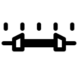
The variometer scale is set using the range. Minimum and maximum values between 3 m/s and 7 m/s can be selected. The default range is 5 m/s.
Log-Scale
[DISABLE]
[ENABLE]
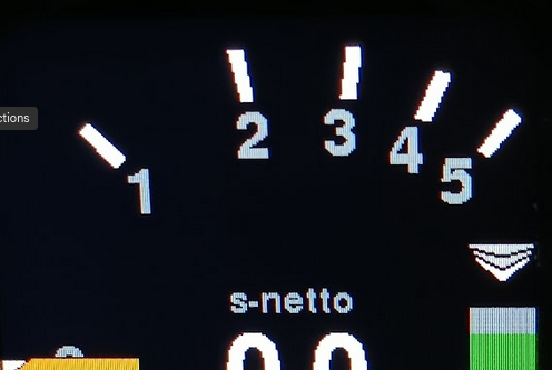
This option allows the variometer pointer display to use a logarithmic scale. The area around zero is expanded, while the extremes of the scale are compressed.
The main advantage is that a much larger measurement range can be displayed without losing resolution around zero. Another key benefit is that relative changes in climb rate are easier to evaluate: for example, a 20% improvement at 1 m/s (an increase of 0.2 m/s) moves the pointer the same relative distance on the scale as a 20% improvement at 5 m/s (an increase of 1 m/s).
Mode
[Gross]    (or Brutto)
[Netto]
[Cruise Netto]
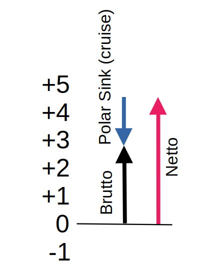
This setting allows you to select whether the variometer functions as a brutto or gross vario, including the gliders sink rate, or as a netto vario, which compensates for the polar sink.
The “Cruise-Netto” option activates the netto automatically when the variometer is in cruise mode. Otherwise, in circling mode the variometer operates as a gross vario, indicating exactly what altitude is gained per second, which is particularly useful when circling, since the MacCready setting is based on the gross climb rate.
The audio signal follows the selected mode. In gross mode, the acoustics only indicate climb when the aircraft is actually ascending relative to the ground, means air mass climb is exceeding the polar sink rate while circling. In netto mode, the audio responds to the net climb: even small lift in the surrounding air is indicated.
This is particularly helpful when flying fast between thermals, as relevant changes in the air mass can be detected more useful, independent of polar sink, because in netto mode the sink rate of cruise flight is compensated, and polar sink make’s a big difference at high airspeeds on low wingloads.
Netto Mode
[Normal]
[Super-Netto]
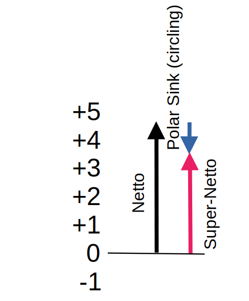
This setting allows further refinement of the netto mode.
In the [Normal] setting, only the polar sink at the current speed is considered, so the variometer display corresponds exactly to the vertical movement of the surrounding air mass. The display indicates this mode with “net” in the top status line.
For example, when circling with a net reading of 2 m/s, the actual gross climb is slightly lower due to the aircraft’s inherent sink when turning. For instance, an LS-4 with a 0.6 m/s inherent sink in a turn would have a gross climb of only 1.4 m/s.
To account for this, the [Super-Netto] setting also factors the inherent sink when circling, specifically the sink that occurs at a 45° bank angle flown at the optimal speed. This way, the variometer shows while cruising even fast exactly the gross climb you would achieve while circling at that point.
In the previous example, the display would show 1.4 m/s. This reduces pilot workload, as there is no need to manually calculate the expected climb; the Super-Netto mode directly indicates whether circling is worthwhile. This mode is indicated with “s-netto” on top of it’s value.
Vario Damping
Vario Damping
Damping
4 sec
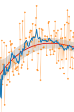
Damping sets the time constant used to smooth the variometer needle display. Because thermals are naturally turbulent, an undamped display is often too noisy to be useful. Typical time constants are a few seconds such as 3 seconds to 6 seconds.
Excessive damping with simple low-pass filters causes noticeable delay. The further optimized Kalman filter of the Pur version used here accounts for physical conditions and predictive behavior, allowing fast response without a nervous display.
Default: 4 seconds
Range: Up to 10 seconds for an even smoother indication might be selected
Averager
25 sec
Damping controls the time constant used to smooth the digital average variometer reading, displayed at the top center of the screen. The default setting is 25 seconds, meaning the display shows the average climb rate over the last 25 seconds what is a typical duration for one circle in a normal glider.
This value is common in many variometer systems and provides the pilot with a useful indication of current thermal strength.
Damping can be modified from 7 to up to 50 seconds if a smoother, a larger value is useful if a more stable average is desired.
Too little damping results in a nervous, hard-to-read display that conveys little useful information.
Climb Statistics
The Mean Climb settings determine how the glider’s average climb rate is calculated for MacCready purposes, filtering out low climbs, averaging over recent thermals (default 45 minutes), and updating at defined intervals (default 60 s) to provide a stable and responsive indicator of thermal strength. Thresholds like Minimum Climb and Major Change control which climbs are counted and when the MacCready dot visibly reacts.

Minimum climb
0.5 m/s
This setting defines the minimum climb rate that is considered when calculating the average climb. Small climb values, such as those encountered during high-speed straight flight, can be excluded. Modern recommendations (see About Gliding) suggest using only the core climb while circling for the MacCready value, and ignoring climb values during straight flight or centering. The default value is 0.5 m/s.
Duration
45 min
According to current recommendations, the climb rates from the last three thermals should be considered when calculating the average climb for the MacCready value. Analysis of many flights shows that a new updraft area is typically encountered about every 15 minutes. To account for this, the default setting for “Mean Climb Duration” is 45 minutes, meaning that only climb values from the last 45 minutes are included in the calculation. This value can be adjusted in one-minute increments.
Cycle
60 sec
This setting determines how often the mean climb is calculated. The “Mean Climb Cycle” defines the calculation interval. The default is 60 seconds, and it can be adjusted between 60 and 300 seconds. For reference, a circle with a 45° bank angle typically lasts about 20 seconds in a glider, so 60 seconds corresponds to roughly three circles. This interval is sufficient to gather enough data for the Mean Climb indicator and to clearly display the trend (via the color of the dot). Shorter intervals produce smaller values and tend to weaken the trend indication.
Major Change
0.50 m/s
This setting defines the threshold for a change in mean climb value. When the climb delta exceeds this value, the shape of the route symbol changes, and the diamond lengthens upward or downward. The default value is 0.5 m/s.
TE Compensation
With the electronic TE compensation feature, it is optionally possible to achieve total energy (TE) compensation for the variometer without a TE – probe. The principle of operation is essentially the same as conventional total energy compensation.
For the TE probe compensation choose the Probe method. For the probe-less electronic compensation choose the eComp method and set an appropriate eAdjustment factor.
A detailed discussion of the parameters affecting TE probe compensation can be found in the paper compiled by Mr. Brözel from ILEC: Total Energy Compensation In Practice (pdf)
Method
[Probe]
[eComp]
The default setting, [Probe], means the external compensation through the TE-probe is applied. This is at the moment the default approach for most gliders equipped with a TE probe.
Selecting [eComp] enables electronic compensation. Useing the eComp does not require to connect the pneumatic TE port of the variometer. A good practice would be to connect the TE port at least with the static pressure.. Only the ST port (static pressure) is used. This method calculates potential energy from true airspeed and combines it with the potential energy from barometric altimeter to generate the proper TE compensated variometer indication.
The eComp is mathematically more precise and overcomes dynamic effects by use of the AHRS sensor to improve the usability of the variometer beyond the capability of a TE-probe.
eAdjustment
100.0 %
The electronic Total Energy Compensation (eTEK) can be fine-tuned using the eAdjustment parameter. The compensation factor is adjustable from 80.0% to 100.0%.
This factor scales the theoretical kinetic energy that is converted into potential energy during changes in airspeed:
TEK = dh/dt + (eAdj/100)(TAS² / 2g).
where:
- dh/dt = measured vertical speed
- TAS = true airspeed
- g = gravitational acceleration
Adjustment Procedure
Perform several smooth push-over and pull-up maneuvers in calm air, for example between 100 km/h and 150 km/h, while observing the variometer indication.
- If the variometer indicates a climb (e.g. +1 m/s) during a pull-up when no air mass movement is present, the compensation is too low (under-compensation). Increase the eAdjustment value.
- If the variometer indicates sink (e.g. −1 m/s) during a pull-up in still air, the compensation is too high (over-compensation). Decrease the eAdjustment value.
Repeat the procedure until pull-ups and push-overs produce little or no indication on the variometer in calm air.
Damping
If the compensation cannot be optimized satisfactorily, increase the variometer damping from the default 4 seconds to 5 or 6 seconds. This reduces transient indications caused by horizontal gusts, turbulence, or rapid airspeed changes.
Even with increased damping, the optimized Kalman Filter remains sufficiently responsive to genuine changes in climb or sink rate.


