
G-Load Display #
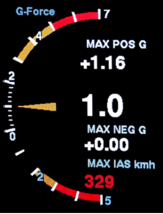
The G-Load Display is an option from the XCVario Series 21 (ff) to display the load factor. If the option is activated, the maximum values are also stored in the non-volatile memory, shown in the G-Load display or can be called up in the setup menu of the G-Meter. It can be set under “System/Hardware Setup/Rotary Setup/Screens” to display the G-meter alternately with the variometer display at the push of a button. In addition, the maximum IAS below the peak value of the negative load factor is also displayed. The peak values are displayed in red as soon as the configured limits have been exceeded.
Activation Mode #
[Off]
[Dynamic]
[Always On]
The display of the load factor can either be deactivated [Off] by default, take place dynamically [Dynamic] and occur when the set thresholds for positive or negative load factor are exceeded, or it can be permanently activated [Always On], e.g. for aerobatics.
Positive Threshold #
5.0
This defines the threshold for the positive load factor in g (multiple of the gravitational acceleration) at which the “G-Load” display shows. A “1” or 1 g corresponds to normal gravity, the acceleration of gravity. The default is 5 g. The value as well as the following settings can be adjusted in steps of 0.1 g.
Negative Threshold #
-3.0
The same setting as in the previous point, only for the negative load factor. The default is -3 g.
Red positive Limit #
4.0
The positive limit of the load factor as relevant for the specific aircraft type. The value can be found in the flight manual. The scale shows when this load factor is exceeded as a red area. The default is 4 g. An acoustic warning signal also sounds when the set maximum permissible positive load factor is reached.
Yellow positive Limit #
3.0
Second, reduced positive limit for the load factor for the value that applies outside the range of the maneuvering speed, for example. The value can be found in the flight manual. If there is no value there, then the value can be set equal to the previous limit, a yellow area does not then appear. The scale shows when this load factor is exceeded as an orange area. The default is 3 g.
Red negative Limit #
-3.0
The same setting of the limit as in the previous point, only for the negative load factor. The default is -3 g. If the limit is exceeded, an acoustic warning signal sounds here too.
Yellow negative Limit #
-2.0
The same setting of the limit as in the previous point, only for the negative load factor. The default is -2 g.
Max Positive #
Display the lowest measured value of the load factor since the last reset.
Max Negative #
Display the highest measured value of the negative load factor since the last reset.
Alarm Volume #
100 %
Alarm Volume that is applied during an G-Load alarm.
G-Load reset #
[Reset]
[Cancel]
With this the stored maximum values of the previous two points can be reset.


What is the max pos and max neg measuring range of the sensor / the instrument ?
If the glider is capable for +7…-5g, the display should show more than that, e.g. +9…-7g or +8…-6g.
The inertial sensor itself is technically capable of measuring accelerations up to ±16 g. However, for this instrument the configured and usable measurement range is limited to ±8 g. As a consequence, values beyond +8 g or −8 g cannot be displayed or evaluated, so a display of +9 g is not possible.
This range was chosen deliberately, as it comfortably covers mostly the operational load factors of sailplanes while maintaining optimal resolution and noise performance within the relevant envelope.
In addition, AHRS data is required by the system not only to provide the G-load information, but also for accelerated-flight corrections, such as calculations of the accelerated gliding polar or for attitude indicator. This makes reliable attitude and acceleration data essential for the overall functionality of the instrument.