
RS232 Interface S1 #
The RS232 interface is used to output the serial OpenVario data (TX) and as a serial to Bluetooth bridge (RX) to connect another serial device, e.g. a Flarm with the device on which XC Soar is running.
Baudrate #

[Serial OFF]
[4800 baud]
[9600 baud]
[19200 baud]
[38400 baud]
[57600 baud]
[115200 baud]
Under this option, the speed can be set between 4800 and 115200 baud in the usual baud rates, or switched off [Serial OFF]. The interface is preset to the baud rate of 19200, which is also preset for FLARM. The speed setting always applies to both directions RX and TX. The default setting is perfect for normal operation of the FLARM to receive GPS data, baro and data from other aircraft. For regular downloads of longer flights, it is recommended to set a higher data rate. For example, with the data rate 57600, which is the highest supported by the Classic FLARM, longer flights can also be loaded in an acceptable time, which has proven to be stable in various applications. Tests on Power Flarms of the newer generation which support higher data rates also ran stably with 115200 baud. Of course, the higher data rate can remain the same for normal operation. The data rate must of course be set the same in FLARM.
Serial Loops #

[Disable]
[Enable]
This option directs data from the receive direction of the serial interface to the send direction. The setting relates to the source of the data. For example [Enable] means routing of the data received on the receiving side (RX) to the transmission direction (TX).
The mode is only supported on S1, and is required, for example, if two devices are connected to an XCVario-20 device with only one interface, e.g. a FLARM on serial RX and an OpenVario on serial TX, and the data from the FLARM is also looped to the OpenVario should. However, this mode does not allow bidirectional communication with the respective devices, so no flight download from the Flarm and no synchronization of MC, ballast, bugs synchronization of XCSoar to the Vario is possible.
S1 Routing #
With this setting, the data from all other interfaces can be routed to the serial interface S1.
The routing is always bidirectional, i.e. in addition to the sending direction, the receiving direction, i.e. the return direction, is also routed.
In the default setting for S1, the wireless interface is set to Enable, i.e. the coupled device is connected via WiFi or Bluetooth to a device on the serial interface S1.
This means that both the commands from the navigation device, e.g. from XCSoar, e.g. to control a radio device, and the messages that the device sends are routed back to the XCSoar.
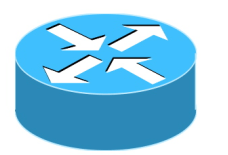
The following figure shows the total of five interfaces of the router as they are named both in the setup menu and also here in the documentation.
XCVario #
[Enable]
[Disable]
With this setting to “Enable” you select whether data of the XCVario should be output on the S1 interface and whether commands should be received and processed via this interface.
Wireless #


[Enable]
[Disable]
This setting routes the data between S1 and the wireless interface, depending on the Bluetooth or WiFi setting. With this setting, the XCVario works as a Bluetooth or WiFi bridge and transparently forwards data from a wirelessly coupled navigation system with e.g. XCSoar to the serial interface S1. Data from other sources are switched to the interface one after the other using the time multiplex method.
S2-RS232 #
[Enable]
[Disable]
With this setting, the data is routed between S1 and interface S2 and vice versa. This is of interest, for example, if a Flarm is connected to S1 and an OpenVario is to be operated at S2. This setting supports, for example, the possibility of connecting a serial FLARM to S1 and an OpenVario to S2 on the main device.
CAN-bus #

[Enable]
[Disable]
This setting routes the data between S1 and the CAN bus, e.g. if they are also relevant on the secondary display. For example, if a FLARM is connected to the front device and its data is routed there to the CAN bus, it can be routed to S1 on the second display so that the FLARM data is available, e.g. for an OpenVario on S1. In this case set this setting to Enable.
TX Inversion #
[Normal]
[Inverted]
According to the RS232 standard with real RS232 levels, mostly realized by a dedicated level conversion chip, a negative logic is actually used. A logical one is represented as minus 15 volts and a zero as plus 15 volts. With the RS232 “TTL”, as is usual with most avionics devices (although rarely mentioned in the manual), there is this level conversion and not, the RS232 TTL levels used there are usually 0 volts for zero and plus 5 volts for a one . In order to send to an RS232 TTL device with the correct logic, the default [Inverted] should be left as is. Devices with real RS232 level converters (plus/minus 15 volt level) usually also understand the voltages 0 and 5 volts that the RS232 TTL supplies, but need 0 volts for a one and 5 volts for a zero, there the setting would be [ Normal] necessary. The voltages are actively limited at the input of the XCVario, so the XCVario can also process the higher levels.
If the setting is correct, the connected device responds correctly to commands sent and readable characters appear in the NMEA device monitor of the navigation system. The XCVario works with 3.3 volt levels, but external 5 volt hardware is compatible with it, since with the TTL standard the one is already reliably recognized from a level at the input of 2 volts, and 3.3 volts are significantly higher.
RX Inversion #

[Normal]
[Inverted]
As with the TX (transmission) inversion but for the receiving side. Default is [Inverted] for RS232 TTL. Normally the setting is identical to the setting for the TX line. To check, look at the data in the XCSoar device manager, if readable ASCII characters appear there with the correct baud rate, the setting is correct.
Twist RX/TX Pins #

[Normal]
[Twisted]
With this option, both a serial device with (DTE) interface, i.e. terminal such as FLARM, and a device with (DCE) i.e. modem or computer, such as an OpenVario, can be connected to the XCVario. In general, the following applies: With RS232 serial lines, a connection named TX at the other end must be switched together with a connection named RX. If the device at the other end is also labeled with TX on pin 4, then the XCVario turn the pins with the “Twisted” (or Swapped) setting to enable a connection with 1:1 standard patch cables. The normal setting means pin 3 = TX and pin 4 = RX. In twisted (or swapped) mode, pin 3 = RX and pin 4 = TX at the IGC standard end of the usual Flarm cable set connected S1, or directly at the IGC compatible S2 port.
TX Line #

[Disable]
[Enable]
With the help of this option, the transmission line (TX) of the S1 interface can be switched off in the [Disable] setting. Then only the data arriving in the receiving direction of interface S1 (RX) is evaluated, the transmission line remains high-impedance.
The feature is required if two devices are to be connected to the external source (e.g. FLARM) using a simple passive 1:1 splitter (RJ45 T-piece) and 1:1 standard cable 8P8C is to be used. In [Disable] mode, the FLARM cannot be actively accessed from the XCVario, e.g. to declare a flight task or to download a flight.
Monitor #
[Disable]
[Start S1 RS232]
Data monitor for S1 serial RS232 interface (same as in Wireless menu but shortcut for S1 RS232 in here). [Start S1 RS232] will start the data monitor a short press to the rotary button is to start/pause the monitor, a long press to terminate the data monitor.
RS232 Interface S2 #
The second RS232 interface, from series 2021, is primarily used for communication with a serial OpenVario data (TX) device, e.g. for an OpenVario or a serial Kobo, or in the case of a wireless device as a serial to wireless bridge to connect another device to the wireless to connect devices. Various devices are possible, various radio devices that your Navi supports, e.g. a KRT2 or ATR833 radio device (fixed baud rate 9600 baud) can be connected here.
Baudrate #
[Serial OFF]
[4800 baud]
[9600 baud]
[19200 baud]
[38400 baud]
[57600 baud]
[115200 baud]
The baud rate is set in the same way as for Interface S1, the same baud rates are supported.
S2 Routing #
With this setting, each of the four other data sources or sinks can be routed to the serial interface S2.
The default is via wireless: Enable, i.e. the coupled device, either via WiFi or Bluetooth, is brought together with a device on the serial interface S2. This means that both the commands from the navigation device, e.g. from XCSoar, e.g. to control a radio device, and the messages that the device sends are routed back to the XCSoar.
XCVario #
[Enable]
[Disable]
With this setting to “Enable” you select whether XCVario data is to be output at the S2 interface and whether commands are to be received and processed via this interface.
Wireless #
[Enable]
[Disable]
This setting routes the data on S2 to the wireless interface, depending on the Bluetooth or WiFi setting.
S1-RS232 #
[Enable]
[Disable]
With this setting, the data is routed from S2 to the S1 interface and vice versa. This is of interest, for example, if a Flarm is connected to S1 and an OpenVario is to be operated at S2. This setting supports the possibility of connecting a serial FLARM to S1 and an OpenVario to S2.
CAN-bus #
[Disable]
[Enable]
This setting routes the data between S2 and the CAN interface, e.g. if they are also relevant on the secondary display.
TX Inversion #
[Normal]
[Inverted]
Identical to the function as with S1, only here for the interface S2.
RX Inversion #
[Normal]
[Inverted]
Identical to the function as with S1, only here for the interface S2.
Twist RX/TX Pins #
[Normal]
[Twisted]
Identical to the function as with S1, only here for the interface S2.
TX Line #
[Disable]
[Enable]
Identical to the function as with S1, only here for the interface S2.
Monitor #
[Disable]
[Start S2 RS232]
Data monitor for S2 serial RS232 interface (same as in Wireless menu but shortcut for S2 RS232 in here). [Start S2 RS232] will start the data monitor a short press to the rotary button is to start/pause the monitor, a long press to terminate the data monitor.
CAN Interface #
The XCVario-22 hardware from around October 2021 also has a CAN bus interface as an option for data transmission to a second device and for connecting future hardware. For devices without CAN, leave the settings at CAN-OFF as shown here in bold (default setting). The CAN bus supports cable lengths of up to 20 meters.
Datarate #
[CAN OFF]
[250 Kbit]
[500 Kbit]
[1 Mbit]
The data rate can be set here. It is recommended to use the 1 Mbit setting, which works without problems over the short distance on the plane and is far outside the spectrum of the radio.
CAN Routing #
With this setting, any data source or sink can be routed to the CAN bus. The routing is always bidirectional, i.e. in addition to the sending direction, the receiving direction, i.e. the return direction, is also routed.
The default is “Disable” for all data, because this only makes sense if a second display is to be connected and synchronized via the CAN bus.
XCVario #
[Disable]
[Enable]
With this setting to “Enable” you select whether XCVario data is to be output on the CAN bus and commands are to be received and processed via the CAN bus. It assumes that the other party also routes the corresponding data to the CAN bus.
Wireless #
[Disable]
[Enable]
This setting routes the data between the CAN bus and the wireless interface, depending on the Bluetooth or WiFi setting.
S1-RS232 #
[Disable]
[Enable]
With this setting, the data is routed between S1 and the CAN bus and vice versa. With this, for example, the data of a Flarm can be transmitted to S1 via the CAN bus to the second display.
S2-RS232 #
[Disable]
[Enable]
The same functionality as with “S1-RS232” visible here in the setup for the S2 interface.
Mode #
[Master]
[Client]
[Standalone]
This setup is essentially relevant when two devices are connected to the CAN bus in a two-seater. “Master” must then be set for the front device and “Client” for the rear device. Otherwise the mode remains on “standalone” which is delivered by default.
Caution: If the mode master is selected for a standalone device, a dummy load is created by the traffic that is sent to the second device but not confirmed. The standalone setting is therefore optima


