
DISPLAY Setup #

All settings related to the display.
HW Type #
[UNIVERSAL]
[RAYSTAR]
[ST7789]
[ILI9341]
The display is pre-configured at the factory with the correct default settings corresponding to the installed display type. Changing the [Type] setting offers no benefits and may even degrade the accuracy of the displayed information. Therefore, adjustments to this setting are unnecessary.
Style #
[Airliner]
[Retro]
[UL]
This feature allows you to switch the graphic display mode between “Airliner” style, “Retro” (or Pointer) style, and “UL” style. The previous colored bar display is part of the Airliner style, while the Retro (Pointer) style uses a semicircular display with a pointer, similar to traditional mechanical variometers. Both display modes are explained in greater detail in the corresponding chapters at the beginning of this document.
A new addition is the UL style, which omits the speed-to-fly display and MacCready value specific to gliding. Instead, it displays the QNH value, catering to ultralight pilots.
Color Variant #
[W/B]
[B/W]
This option allows you to switch the display color between “W/B” (white on black) and “B/W” (black on white). The default setting is W/B, as it is easier to read in sunlight and gentler on the eyes due to its lower light intensity. The inverted B/W setting is also available and may be preferable if other instruments or the panel use a similar color scheme.
Orientation #

[NORMAL]
[TOPDOWN]
By default, the device is configured for installation on the left side of the panel, with operation performed using the left hand on the left edge of the display. For installation on the right side, the display orientation can be inverted using the [Orientation] setting, which moves the rotary knob to the opposite side. The available options are [NORMAL] and [TOPDOWN].
Needle Alignment #
[Front]
[Back]
This setting allows you to choose whether the variometer needle is displayed in the foreground ([Front])—overlapping information within its area, such as altitude and wind data—or in the background ([Back]), positioned behind this information.
Display Test #
[Cancel]
[Start]
Factory display test for a fully white and black screen in order to detect faulty pixels.
Rotary Setup #
Screens #
If you prefer to switch only between screens without entering the Setup menu, the Setup function can be assigned to a long press, as described in the previous section. In this configuration, a short press will toggle exclusively between the variometer screen and other screens activated in this menu. Otherwise, with each press of the rotary button, the XCVario cycles through screens such as Variometer > G-Meter > Setup.
G-Meter #
[Disable]
Enable
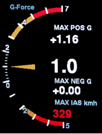
The “Screens” menu allows you to select which screens are accessible by briefly pressing the rotary button. By default, only the variometer screen is displayed, and the button toggles between the variometer and the setup menu. To include the G-Meter screen in the rotation, simply enable this option in the menu.
Horizon #
[Disable]
Enable
The XCVario, equipped with an IMU and AHRS, offers a simple horizon display for situational awareness, similar to the horizon in XCSoar. The display is square and features a pitch scale. It can be activated via the Screens menu as described previously. Small lines on the scale represent a 5° inclination, larger lines indicate 10°, and the top line corresponds to a 40° inclination.
Important: The horizon is not intended as a blind flight instrument. Instead, it serves as a tool for training and monitoring, such as maintaining the optimal bank angle of 45° or the ideal angle of attack during thermaling. It provides sufficient accuracy for these purposes under normal flight conditions.
Direction #

[Clockwise]
[CounterClockwise]
The direction of rotation of the rotary switch (rotary) can be reversed if the rotary switch used has a different coding. This setting is made in the factory and does not normally need to be changed. After a factory reset it may be necessary to make this setting again.
Sensitivity #

1 Indent
2 Indent
3 Indent
4 Indent
This allows you to adjust the sensitivity of the rotary switch. There are rotary switches which deliver two pulses per detent (indent). In this case, “2..4 indent per increment” is announced, since otherwise a point would be skipped during a detent. The optimal setting is made in the factory and normally does not need to be changed. It has proven useful to select a setting with “2 Indent” per increment (default setting) so that you do not accidentally move a line or a value when you press the rotary knob.
Rotation #
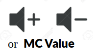
[Volume]
[MC Value]
The presetting for the rotary switch (English Rotary Default) determines which setting is changed in Vario mode by turning the rotary. You can choose between [Volume] for the volume and [MC Value] for the MC value. The default is [Volume]. If the volume control is not required, e.g. when using an external audio device with its own volume control, or if changing the volume via the setup is sufficient, the MC value can also be used here.
The setting [MC Value] makes sense if the audio function is implemented via the external audio input of the radio device, the internal loudspeaker is then switched off. In this case, the volume control of the radio is used, so the rotary can take over the other function.
Setup Menu by #

[Short-Press]
[Long-Press]
This setting can be used to select whether the XCVario should activate the setup menu with a brief press of the rotary button (less than half a second) or with a long press of the button. In the “Short-Press” presetting, a short press on the rotary activates the setup menu. If you want to use the feature and switch back and forth between different display screens with a short press, see next heading, it makes sense to first activate the setup menu with a long press. The short press is therefore available to change the display to the next screen.
Gear Warning #

[Disable]
[S2 Flap positive]
[S2 RS232 positive]
[S2 Flap negative]
[S2 RS232 negative]
[External]
With the “Gear-Warning” a warning can be triggered in the case of extended brake flaps and retracted landing gear. The magnetic contact on the brake flap must be closed when it is retracted, and the contact on the landing gear when it is fully extended.
Please Note: The warning can be acknowledged by pressing the rotary and then turns off for 500 seconds or about 8 minutes.
Both contacts are switched in parallel with one end connected to ground (GND, battery minus) and the other end connected to pin 6, the flap sensor input, to S2 and connected to +12 volts via a pull-up resistor. Alternatively, pin 4 on S2, the RX pin of the RS232 interface, can be used, and there is an option for external [External] commands that can be send by an external device in order to trigger the gear warning, see the „$g“ commands section for details about this.
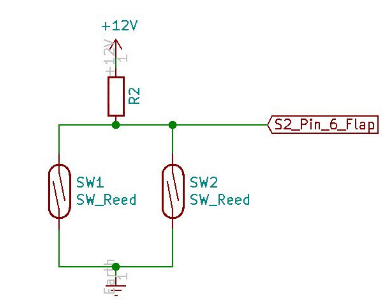
The warning is given optically with the display ! GEAR ! , as well as an audible warning tone, and has priority over the other screens, with the exception of the stall warning.
The feature is available if either the flap sensor or the RS232 interface is not configured, i.e. setting: Disable is mandatory there and is switched off by default, or if you don’t use the flap sensor input.
The switching of the two magnet contacts is shown on the right, both must be designed as normally open contacts, i.e. they must be shot in the vicinity of the magnet. The pull-up resistor R2 is necessary for a high-level and should be in the 100 to 150 Kilo-Ohm range and at least 1/8 watt of power.
With the “negative” options you can also use contacts, which are to be laid in series and then close when the flaps are not locked, or the landing gear is not fully locked.
AHRS Setup #
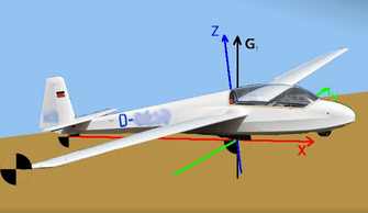
Add devices starting with 2021 series of the XCVario feature an 6 axis AHRS (IMU) sensor chip, which has a sensor for the acceleration in all three axes and a gyro for the rotational speed also in all three axes.
The sensor is used to record the acceleration or the load factor (G-Load), e.g. when circling, which in principle has the same effect as additional ballast, i.e. an increase in the optimal drive, as well as input for the position indicator (artificial horizon) and to deliver the load factor to XCSoar.
AHRS ID #
The four-digit “AHRS ID” is required to generate the license key for the AHRS feature. If the feature was not ordered directly with the device, this ID must be specified when ordering the AHRS feature. The AHRS ID is not changeable.
AHRS Option #
[Enable]
[Disable]
IIn the default setting and with a set license key (license key), the sensor is Enabled, otherwise Disabled. The option can only be set to Enabled if a valid key is present. With this setting, the processing of the sensor data can be switched off. When switched off, the data fields for the roll angle and the pitch are not forwarded in the NMEA sentences, the corresponding fields remain empty in this case.
AHRS Calibration #
The AHRS Calibration catches the inertial sensor orientation with respect to the glider. As a result a small misalignment of the XCVario panel mount does not propagate into its calculation. Specifically the Yaw, that means the gliders longitudinal direction is registered, additionally to zero Pitch and Roll angle.
Axis calibration #
[Cancel]
[Start]
[Reset]
According to the manufacturer’s instructions, the sensor must be zeroed once in its installation position for maximum accuracy. There is source of misalignment not only as of minor angle deviations within +-1° from chip tolerances and soldering the chip, moreless also as of installation position of the device in the instrument panel that is usually a bit different from the exact horizontal attitude of fuselage. It is possible to set the sensor to zero with regard to pitch and bank by this procedure on the ground:
To start the calibration procedure, the glider must to be placed be on a ground that is not inclined, a ground that as flat as possible (check with a spirit level) usually hangars or aprons should be leveled enough for that purpose. Start the procedure by select [Start] and follow the procedure.
You will get prompted to place first the right wing tip down on the ground, and then the left wing. Each step is to be confirmed by pressing to the rotary button. The procedure is completed when both wings are done and the “Finished Success” message appears. The angle the airplane has been shifted will be displayed. After that you may check attitude with the horizon if pitch and bank is correct.
The minimum shift angle is 8° in total that is needed. Smaller angles will result in an Error printed. If this can’t achieved e.g. in an open class glider with large wingspan and low V-Angle, try procedure e.g. without the outer wing or wing extensions. Take care the tip with a foam in that case, if unprotected. If even this is not possible, try to raise the glider in the middle e.g. in assemble position on the fuselage car at your trailor or push it on a ramp with enough height.
Ground angle of attack #
12°
Adjust your ground angle of attack, which is included with the above calibration procedure. This can be done independently and after the AHRS calibration. It will align the zero horizon pitch to horizontal flight. Best case is to put the zero pitch to the speed of best L/D usually around 100 km/h in a modern glider (check manual). Raising the ground angle of attack lowers the horizon on the display. The “Ground angle of attack” defaults to 12°.
AHRS License Key #

[First Letter]
[Second Letter]
[Third Letter]
[Last Letter]
The four-digit license key for activating the AHRS sensor can be entered via this menu item. 4 letters, numbers or special characters are possible, resulting in several million possible combinations. If the feature is purchased, the license key is set accordingly.
The key is not overwritten during a factory reset.
Note: The AHRS sensor is used to take the load multiple into account for the stall warning and for the polar to precisely calculate the target travel. The variometer has a simple screen for an artificial horizon, and when activated, the data is also forwarded to the flight situation (English situation awareness). Under no circumstances this simplified screen is intended to fly into IMC conditions.
The license key can only be entered on the ground.
AHRS Parameters #
Here parameters of the attitude and heading reference system can be tuned. Normally no change is required. Changes can cause changes and inaccuracies in the artificial horizon, so normally do not make any changes here. The optimal default setting is the value printed here in bold.
Gyro Max Trust #

100x
This factor determines the maximum trust in the rotation angle sensor (gyro sensor) compared to the acceleration sensor for the position indicator. The 3D vectors of the acceleration sensor, cleaned of the centrifugal force, are merged with the values for the rotation angle of the gyro sensor; the optimal value is as high as possible without the gyro drift causing static position deviations.
Gyro Min Trust #
20x
This option changes the minimum factor of the sensor fusion of the rotation angle sensor (gyro sensor) and the acceleration data for the position indicator. This factor is always active, regardless of the loadfactor.
Gyro Dynamics #
5.00

The factor says by which dynamic factor the maximum trust in the gyro is multiplied at a loadfactor unequal to 1.0. At loadfactor around 1.00, the acceleration values are more trusted because they work very precisely and, above all, drift-free. However, these values are unusable during accelerations, and the gyro is therefore more trusted to continue to correctly represent the position in space in this phase. The formula for the multiplier is 10 ^ ( (Load multiple – 1) * Gyro_Dynamics) -1.
Gyro Roll Check #
[Disable]
[Enable]
Beta feature at that time that enables the latest algorithm for roll angle. Needs flight testing so disabled per default at the moment. Feature shall improve accuracy of bank angle.
Gyro gating #

1.00°
Gyro gating can be used to suppress the drift of the gyro around the zero point. A specification of 1.00° means that smaller rotation speeds of less than 1.0° per second are hidden.
Gyro calibration #
1.07
The gyro may need to be adjusted and calibrated to provide an accurate response. The factor chosen is an average over a series of measured sensors to obtain the correct angle when the device is rotated, e.g. B. at 45° the result should also be 45°.
Reset to Defaults #

[Cancel]
[Start]
The default values for the AHRS parameters from the last chapter can be reset to the default values by entering [Start]. This can be helpful if the values have been changed manually or come from an older software version, but these have meanwhile been further developed in newer SW versions.
AHRS Temp Control #
45
From hardware revision starting XCVario-23, the temperature of the AHRS chip can be adjusted to keep a constant value. The feature improves the accuracy of the G-meter and angular rate sensor (gyro) through the constant temperature, and thus the accuracy of the horizon. The default is 45° Celcius. The temperature can be reduced for northern areas, or increased for southern areas. A setting of -1° Celcius disables the feature. This increases the power of the device by a maximum of 0.3 watts or about 20 mA at 12V. Normally, only a part of the power is used, the control reduces the power when the set temperature is reached via a PWM signal. A temperature of about 35° Celcius above the ambient temperature can be reached. With a setting of 45°, the temperature remains constant in an ambient range of 10° to 45°. The feature is automatically switched on with hardware revision -23. If the temperature is set correctly, the unit is shown in gray (°C) at the top left of the display as usual. If the temperature is more than 0.5 degrees higher, the unit is shown in red (°C) or if the temperature is too low in blue (°C).
AHRS RPYL Sentence #

[Disable]
[Enable]
This can be used to activate a data set as generated by a Levil AHRS. The $RPYL as well as an $APENV1 data record are generated. The data sets contain AHRS information such as pitch, roll and yaw (the latter if a magnetic sensor is installed), the load factor in the Z direction (vertical), as well as the altitude and airspeed and the TE variometer information. The feature is switched off by default [Disable], and is only required for programs that support it, the idea behind it is e.g. to operate a sky map, which is currently being tested.
AS Sensor type #
[ABPMRR]
[TE4525]
[MP5004]
[Autodetect]
Different sensors for airspeed (airspeed, abbreviated: AS) are used. The 2020 series was delivered with the sensor type MP5004, in 2021 the TE4525 and later the ABPMRR were used. The setting is made at the factory and does not need to be changed. With [Autodetect] an attempt is made to automatically recognize the correct setting at the next start.
Attention:
The ABPMRR and TE4525 types are indistinguishable at their interface, but have differences in mechanics and behavior and must therefore be set manually. The method of detecting the sensor via Autodetect cannot be used here. The correct type must be set manually. This can be the case when updating from older software versions.
Factory Voltmeter Adj #
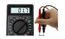
-0.00 %

12.75 Volt
Dialogue which can only be used in the factory to precisely fine-tune the battery voltage measurement in order to achieve maximum accuracy. If the adjustment has already been made, the dialog will be suppressed at the next start. After a factory reset, the dialog appears and enables precise adjustment. Without this setting, the measurement is accurate to about 1%. A multimeter is required to carry this out, with which the voltage can be measured exactly.


You mention that the option AHRS needs to be ordered.
Is the license key included in the price, displayed in the shop site ?
It refers to AHRS being available, but I see no choice ogf options when I add it to the shopping cart.
If not included, what is the price for this license key ?
Question solved: AHRS license key is available in the shop under “extensions”.