
The settings for the vario display and the speed to fly can be adjusted in the Vario dialog.
Range #
5 m/s
The scale of the variometer is set with the range. A range from 1 m/s to 30 m/s can be selected for the min/max values. Default is 5 m/s.
Log-Scale #
[DISABLE]
[ENABLE]
With the help of this option, the pointer display of the variometer can be shown with a logarithmic scale. The area around the zero point is stretched, and the areas towards the end of the scale are gathered. The mode has the advantage of being able to display a significantly larger measuring range without losing accuracy around the zero point. Another decisive advantage: This means that relative changes can be better evaluated, which means an improvement in climb of 20% at 1 m/s, i.e. an increase of 0.2 m/s, corresponds to the same way on the scale as relative improvement by 20% at 5 m/s, equivalent to 1 m/s.
Mode #
[Brutto]
[Netto]
[Cruise Netto]
With this setting you can choose whether the variometer works as a gross vario, i.e. without taking account of the polar sink rate, or as a netto vario with the polar sink rate being calculated out.
The “Cruise-Netto” setting selects the net setting exactly when the vario is in speed-to-fly mode, otherwise the vario works as a gross variometer, which makes sense when circling, because for the MacCready setting the gross rate is relevant.
Of course, the audio signal also follows the set mode. In the gross setting, the acoustics only report climbing when the surrounding air mass rises faster than the polar sink rate, i.e. the aircraft is actually climbing. In the netto setting, the audio signal is coupled to the net climb, so as soon as the surrounding air mass rises, the acoustics also indicate climb. This makes sense, for example, to better recognize small changes in the surrounding air mass when flying fast ahead, since the sometimes higher sink rate in net mode is otherwise compensated.
Netto Mode #
[Normal]
[Relative]
With this setting, the net mode can be further refined. In the [Normal] setting, only the polar descent is taken into account for the current speed, so the variometer display corresponds exactly to the rise or fall of the surrounding air mass. In the display, this setting for the normal net is signaled with “net” in the top status line.
For example, if you circled the net display at 2 m/s, you would have a slightly less effective (gross) climb than the pure net value due to the inherent sink rate when turning, e.g. an LS-4 with an inherent sink rate of 0.6 m/s when turning only 1.4 m/s.
In order to take this into account, the net mode setting [Relative], often also called “Super Netto” (default), also takes into account the inherent sink rate when circling, specifically the inherent sink rate that occurs when circling with a 45° bank angle at the optimal speed would be. So it shows the value that you would have in terms of gross rises if you circled at the point. The display of the vario would be 1.4 m/s in this case, and further reduces the workload in the cockpit, since one no longer has to calculate the value of the expected climb in order to assess whether circling is worth as displayed directly in Super-Netto mode. This setting is signaled with “s-net” in the status line.
Polar Sink #
[DISABLE]
[ENABLE]
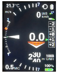
By selecting [ENABLE] (default setting), the polar sink rate is displayed in relation to the speed in the gross mode of the variometer. With [DISABLE] the display can be switched off, the polar sink rate is then no longer displayed. The polar sink rate is shown in the airliner style as a blue bar, in the retro style as a blue arc starting from the zero point and pointing downwards.
Needle Color #
[White]
[Orange]
[Red]
Option for the color of the vario pointer. In the default setting, the vario pointer is white [Orange], but can also be displayed in orange or red (Red).
Center Aid #

[Disable]
[Enable]
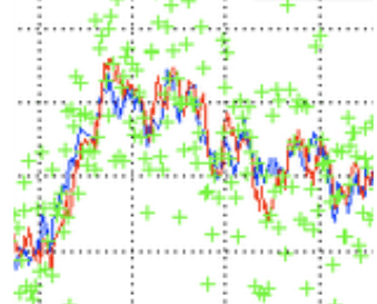
With the option for the center aid, you can choose to show a center aid in the retro display. The default is [Disable], with [Enable] the centering aid is displayed. The feature is still new and has yet to be tested in flight. In the lower half of the scale, it shows green dots on a circular arc, which increase with the strength of the updraft relative to the flight direction (heading), and is intended to support the pilot in shifting the circle accordingly for better climbing. If there is no magnetic sensor, the course over ground from a possibly connected Flarm or GPS is used as a reference.
Vario Damping #
3 sec
Damping controls the time constant for smoothing the variometer display. Normal thermals are inherently turbulent, which means that an undamped vario display provides the pilot with little information that can be evaluated. Time constants of a few seconds are common. Too much damping delays the display with simple low-pass filters. The optimized Kalman filtering, which takes physical conditions into account and thinks ahead, reacts quickly without appearing nervous. The default is 3 seconds. Values up to 6 seconds can be useful for an even smoother display.
Averager #
20 sec
This damping controls the time constant for smoothing the digital average variometer display, top center of the display. The default is 20 seconds, so the digital display shows the average climb over the last 20 seconds. This is a fairly common value in many variometer systems, and gives the pilot an indication of the current strength of the thermal. Insufficient attenuation leads to poor legibility and offers hardly any useful information due to the nervousness of the display. The value can theoretically be increased to 60 seconds.
Mean Climb #
Minimum climb #

0.5 m/s
The Mean Climb min(imum) setting. For the calculation of the average climb, small climb values, which are present, for example, in straight flight at high speed, can be hidden. A modern recommendation (http://aboutgliding.com/005-a-small-error-in-maccready-theory/) In the following, only the core climb when circling should be used for the MC value, and not the climb values in straight flight or when centering. This value defines the minimum climb from which a climb value is still taken into account in the calculation of the mean climb. The default is 0.5 m/s.
Duration #
45 min
According to the recommendations, the climb values of the last 3 thermals should also be taken into account as the average climb for the MC value. From the analysis of many flights you can see that a new updraft area is approached about every 15 minutes. This is taken into account with a default setting of 45 minutes for the “Mean Climb dur(ation)”, i.e. only values from the last 45 minutes are taken into account. The value can be changed in minute increments.
Cycle #
60 sec
This setting determines how often the mean climb is calculated. The “Mean Climb cycl(e)” defines the period in which this occurs. The default is 60 seconds, the value can be tuned between 60 and 300 seconds. A circle with a 45% bank angle usually lasts about 20 seconds with a glider, 60 seconds corresponds to about 3 circles. This is a good value to gather enough data for the new Mean Climb indicator and to be able to clearly show the trend (shape/color of the diamond) accordingly. Shorter times lead to small values and tend to weaken the trend signaling.
Major Change #
0.50 m/s
“Major Change” is the value for the change in average climb, which is graphically represented by a symbol change. If the value is exceeded, the shape of the route changes and the diamond lengthens up or down. The default is 0.5 m/s.
S2F Settings #
Damping #
5.00 sec
The S2F (Speed to Fly) can also be dampened within certain limits, the default is 5 seconds. Greater dampening smoothes but also delays the S2F display, so that after leaving the thermal, the speed to fly does not immediately increase in line with the sink. The value can be set in 0.1 second steps up to a maximum of 10 seconds. In modern aircraft with high wing loading and high cruise speeds of over 150 km/h, it makes little sense to react to short thermals. This would even be counterproductive, since unfavorably high load factors then occur due to inertia, which reduces the performance, which speaks for a damping of the S2F. When lined up, it makes sense to react with constant climbing or in a blue hole with constant falling, which is also very possible with a certain amount of damping. The default value of 5 seconds can be tuned by the user.
Blockspeed #
[DISABLE]
[ENABLE]
By setting the block speed [Enable], the rising or falling of the surrounding air mass (according to the value of the net vario) is suppressed. Only the load and the MacCready value are then included in the calculation of the optimal speed. The speed that the speed command then displays remains constant in the thermal, which follows the theory that pulling up with typical thermals lasting a few seconds does not necessarily make sense due to the inertia of the aircraft. This was proven years ago by numerical simulation at the Technical University of Munich, and it was shown that the MacCready speed for the upwind case only makes sense from a certain thermal duration of approx. 20-30 seconds (half the period of the phygoid or natural frequency, also called pump frequency) , or if you really want to crank. Some well-known pilots fly this style and achieve good average speeds with it.
S2F Mode #
[Vario fix]
[Cruise fix]
[Switch]
[AutoSpeed]
[External]
[Flap]
[AHRS-Gyro]
The S2F ‘Mode’ specifies the procedure used to switch between circling and speed to fly. There are four options. The mode can either be fixed to Vario [Vario] or Speed to Set [Cruise]. The instrument then does not change modes, and remains fixed in either circling or speed command mode. In practice, when flying cross-country, these two settings make little sense, at most the vario mode can make sense if you don’t want to fly according to the speed to fly and always want to see a conventional vario display.
The speed command is always visible, so a speed command is also displayed in “Vario” mode, but this is the optimum circling speed with the current load for the minimum sink in a turn of approx. 45°. The resulting 1.4-fold load factor (+40%) is taken into account with a speed increase of ~20%.
There is also the option of using an external switch, e.g. a stick switch or tactile switch (more modern) on the I panel, better on the stick to change between vario and speed to fly. The switch must of course be operated, which increases the workload in the cockpit, but offers maximum flexibility. If you want to avoid this and if you want the switchover to take place automatically from a certain speed, select [AutoSpeed] (default setting). The speed to switch over can be set in the following menu item: “S2F AutoSpeed”.
In [External] mode, the speed to fly setting is taken over by a second variometer, either coupled via Bluetooth or via the CAN bus from series 2022. The second device can be either the rear or the front variometer, depending on where you put the switches or want to wire the button. Select Switch (or Autospeed) on the device that should react to the switches. On the second device that you want to synchronize, the “External” mode.
Warning: The “Cruise from Master” mode has been replaced by this setting, so synchronization can now also be done from the client.
The [Flap] mode allows you to switch the speed command mode to circling mode via the optional flap sensor. The changeover takes place exactly when the flap exceeds the value of “S2F Flap Pos”.
The [AHRS-Gyro] mode can be used on all devices except the 2020 series, and it automatically switches to circling flight mode if the rotation speed in degrees per second is greater than the “S2F AHRS Deg”. The measured rotational speed is the value averaged over 20 seconds and provided with a hysteresis of 20%, it is only switched back when the value is 20% lower than the set value.
S2F Switch #

[Switch]
[Push Button]
[Switch Inverted]
[Disable]
The type of speed command switch can be set, a switch [switch] is preset, but a button [push button] can also be selected, which changes the setting each time the button is pressed. This can make sense, for example, when using a Stefly stick input device equipped with buttons. The [Switch Inverted] option stands for a switch with the reverse function, i.e. the speed command mode is then selected when the switch is open instead of when the switch is closed. The switch can change mode at any time, even if set to [AutoSpeed], [Flap], or [AHRS-Gyro], unless set to [Disable].
S2F AutoSpeed #
100 km/h
This is the speed in AutoSpeed mode at which the variometer changes from circling to speed command or cruise mode. The default is 100 km/h. With higher wing loading and modern gliders, the value can be set correspondingly higher.
S2F Flap Pos #
1
This setting defines the flap position at which the S2F mode should be switched in the “S2F mode” [Flap]. By default, the flap position is set to +1.
S2F AHRS Deg #
12 °
This sets the threshold for the rate of rotation in degrees per second at which the device switches to S2F mode in [AHRS-Gyro] mode. Small values switch to thermal mode early on when circling, while larger values switch with a delay due to averaging over approx. 20 seconds. A typical circle with a duration of 30 seconds has a rotation rate of 360/30 = 12° degrees per second, which is the default.
Hysteresis #
5 Seconds
With the hysteresis, the automatic, controlled by the airspeed switching (AutoSpeed mode) to target flight can be calmed down. Without hysteresis, the mode may switch back and forth frequently at an airspeed around the set AutoSpeed. A hysteresis of 5 Seconds (default setting) switches to speed to fly mode when the speed is bejond the threshold for the given hysteresis time.
Arrow Color #
[White/White]
[Blue/Blue]
[Green/Red]
The color of the speed to fly arrow can be set individually under “Arrow Color”. The first color is for the up arrow, the second color is for the down arrow. The last arrow is displayed in a different color if the range is exceeded. 3 arrows are displayed with the levels 10, 20 and 30 km/h. If the deviation is more than 30 km/h, the case of exceeding is given.
Electronic Compensation #
With electronic compensation, you can optionally achieve total energy compensation for the Vario without a TE nozzle. The feature is still in the optimization phase, but already works in principle.
Good electronic compensation requires well-placed and functional static and dynamic pressure taps. Many factors play a role here, starting with the mass of the air trapped in the pressure lines, pressure changes along the fuselage and in the wing area, accelerations and more. It is therefore advised to generally use TE nozzle compensation, which works better in most cases. The parameters that play a role in good compensation can be found in the .pdf scan of the following paper, which Mr. Brözel from ILEC compiled at that time: https://xcvario.de/wp-content/uploads/2021/11/GliderInducedErrorsinTotalEnergyVariometry.pdf
eCompesation #
[TEK Probe]
[EPOT]
[PRESSURE]
The default here is [TEK Probe] means no electronic compensation and today is the recommended way once your glider has a TEK probe. The settings [EPOT] or [PRESSURE] enables the electronic compensation. In this modes the TEK nozzle pressure is no longer relevant and in principle does not need to be connected. If those setting is selected, only the pressure connected to ST, the static pressure, is used. This can make sense if no TE nozzle is available. Two different methods are available by today.
The first method [EPOT] calculates from true airspeed the potential energy expressed in meters and joins this with the barometric altimeter to create the vario signal. This method is more accurate in terms of mathematics, hence is more sensitive to dynamic effects what can be an issue in high performance gliders.
The second method [PRESSURE] is new and experimental is based in pressure readings from ST and PI port, and directly joins this pressures in the same way as the TEK probe does. The second method might bring better results in dynamic situations, so maybe more useful for high performance machines, flight tests shall bring a clearer picture here, you may try it yourself and give us feedback.
Adjustment #
0.00 %
Both methods for electronic compensation can be tuned by this parameter. The compensation can be adjusted positively or negatively in 0.1% steps up to +/-50% using this percentage factor. This factor decreases or increases the theoretical kinetic energy, which is converted into height during hoisting (V2/2g). In the case of under-compensation (vario shows increase when pulled up), the value should be increased until the display is correct. The same applies to overcompensation with negative values. It is also advisable to increase the preset damping of the Vario from 3 seconds to at least 5-6 seconds in order to minimize transient effects (short-term deviations). The rapidly converging Kalman filter then still reacts sufficiently quickly to changes.
Similar effect for adjustment is there when the pressure method is used, then this factor applies to the total (PI) pressure that is being subtracted from the static pressure.


